the Creative Commons Attribution 4.0 License.
the Creative Commons Attribution 4.0 License.
 | 19 Jun 2019
Induced seismicity in geologic carbon storage
Víctor Vilarrasa
Jesus Carrera
Sebastià Olivella
Jonny Rutqvist
Lyesse Laloui
Geologic carbon storage, as well as other geo-energy applications, such as geothermal energy, seasonal natural gas storage and subsurface energy storage imply fluid injection and/or extraction that causes changes in rock stress field and may induce (micro)seismicity. If felt, seismicity has a negative effect on public perception and may jeopardize wellbore stability and damage infrastructure. Thus, induced earthquakes should be minimized to successfully deploy geo-energies. However, numerous processes may trigger induced seismicity, which contribute to making it complex and translates into a limited forecast ability of current predictive models. We review the triggering mechanisms of induced seismicity. Specifically, we analyze (1) the impact of pore pressure evolution and the effect that properties of the injected fluid have on fracture and/or fault stability; (2) non-isothermal effects caused by the fact that the injected fluid usually reaches the injection formation at a lower temperature than that of the rock, inducing rock contraction, thermal stress reduction and stress redistribution around the cooled region; (3) local stress changes induced when low-permeability faults cross the injection formation, which may reduce their stability and eventually cause fault reactivation; (4) stress transfer caused by seismic or aseismic slip; and (5) geochemical effects, which may be especially relevant in carbonate-containing formations. We also review characterization techniques developed by the authors to reduce the uncertainty in rock properties and subsurface heterogeneity both for the screening of injection sites and for the operation of projects. Based on the review, we propose a methodology based on proper site characterization, monitoring and pressure management to minimize induced seismicity.
- Article
(4157 KB) - Full-text XML
- BibTeX
- EndNote


The interest in subsurface energy resources, such as geologic carbon storage, geothermal energy and subsurface energy storage, has significantly increased as a means to mitigate climate change (IPCC, 2018). In particular, geologic carbon storage has the potential to store large amounts of carbon dioxide (CO2) in deep geological formations, reducing CO2 emissions to the atmosphere (Hitchon et al., 1999; Celia, 2017). Such subsurface energy-related activities imply fluid injection and/or extraction that change the pore pressure and thus the effective stresses, causing deformation and potentially fracture and/or fault reactivation that may lead to induced (micro)seismicity (Ellsworth, 2013; Grigoli et al., 2017).
Induced microseismicity, i.e., seismicity of such a low magnitude that is not felt on the ground surface (typically moment magnitude M<2), is positive if confined within the injection formation because shear slip of fractures enhances permeability (Yeo et al., 1998; Vilarrasa et al., 2011; Rutqvist, 2015). This permeability enhancement permits injecting the same amount of fluid at a lower injection pressure, thus reducing compression costs. However, induced microseismicity should be avoided in the caprock because its sealing capacity could be compromised, which could lead to CO2 leakage. Additionally, if felt, induced earthquakes may damage wells, buildings and infrastructure and may cause fear and nuisance to the local population (Oldenburg, 2012). As a result of these negative effects, several geo-energy projects have been canceled before they started operation, such as the enhanced geothermal systems (EGSs) at Basel, Switzerland (Häring et al., 2008; Deichmann et al., 2014), and Pohang, South Korea (Grigoli et al., 2018; Kim et al., 2018); a hydrothermal project at Sankt Gallen, Switzerland (Edwards et al., 2015; Diehl et al., 2017); and a seasonal gas storage project at Castor, Spain (Cesca et al., 2014; Gaite et al., 2016). Thus, perceivable induced-seismic events have to be minimized, and ideally avoided in order to achieve a successful deployment of geo-energy projects.
Geologic carbon storage projects, both at large scale and pilot scale, have not induced any perceivable earthquake to date (White and Foxall, 2016; Vilarrasa et al., 2019). This lack of perceivable seismicity may be due to some favorable aspects of CO2 storage with respect to water injection that will be explained in this paper. Yet, induced microseismicity is common, such as projects at In Salah, Algeria (Stork et al., 2015; Verdon et al., 2015); Decatur, Illinois, USA (Kaven et al., 2015; Bauer et al., 2016); and Otway, Australia (Myer and Daley, 2011). Despite the absence of perceivable seismicity to date, proper protocols should be defined and followed to avoid inducing perceivable earthquakes in future geologic carbon storage projects.
The aim of this paper is to review the potential causes of induced seismicity in geologic carbon storage and to explain methodologies that can serve to minimize the risk of inducing perceivable seismic events. First, we introduce the potential triggering mechanisms of induced seismicity and then we go into the details of each of them. Specifically, we review the stress state of deep geological formations, the pore pressure evolution, non-isothermal effects resulting from CO2 injection, shear slip stress transfer and geochemical effects on geomechanical properties, and how these effects may lead to induced microseismicity. Afterwards, we analyze how CO2 injection affects fault stability and, finally, we present subsurface characterization techniques that can be used to minimize the occurrence of perceivable induced seismicity.
The basic principle of induced seismicity is that the pressure buildup caused by fluid injection reduces the effective stresses, which brings the stress state closer to failure (Fig. 1). If failure conditions are reached, the elastic energy stored in the rock mass is released and a (micro)seismic event is induced. Failure in geomaterials can occur either in tensile or shear mode (Jaeger et al., 2009). While tensile failure induces microseismic events of such low magnitude that they cannot be felt on the ground surface, shear failure may lead to perceivable earthquakes if a sufficiently large area of a pre-existing discontinuity, i.e., a fracture or fault, is reactivated. Nevertheless, in the cases in which tensile failure is sought, i.e., to create hydraulic fractures to enhance rock permeability, shear failure of pre-existing faults may also occur if they become pressurized during the hydraulic fracturing operations. In such a situation, perceivable earthquakes associated with hydraulic fracturing operations may occur (Rubinstein and Mahani, 2015). For example, a perceivable earthquake occurred at the Preese Hall 1 exploration well for shale gas near Blackpool, UK, during hydraulic fracturing because a pre-existing nearby fault was reactivated (Clarke et al., 2014).
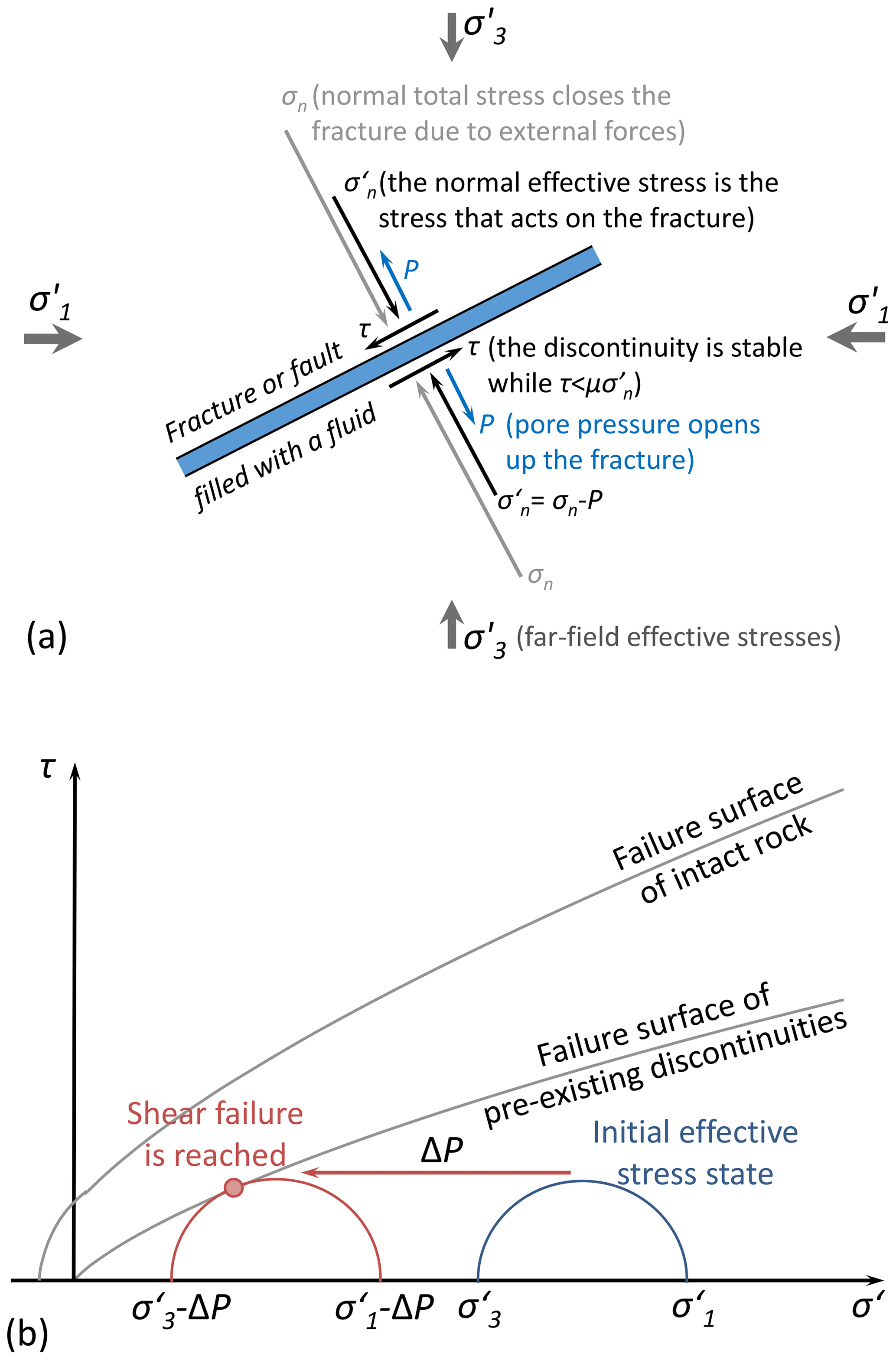
Figure 1(a) Initial stress state of a fracture or fault of arbitrary orientation with respect to the far-field effective stress and (b) Mohr circles showing how the reduction in effective stresses as a result of pressure buildup, ΔP, may induce shear failure in pre-existing discontinuities, i.e., fractures or faults. and are the maximum and minimum principal effective stresses, respectively, τ is tangential stress, is normal effective stress to the fracture or fault, and μ is the friction coefficient. The failure surface has been plotted by considering the nonlinear failure criterion (Barton, 1976).
In principle, fluid pressure buildup may seem the only mechanism that induces seismicity. Thus, intuition suggests that stability should improve in the vicinity of the injection well after injection is stopped because fluid pressure drops rapidly. Far away from the injection well, fluid pressure continues to rise and thus pressure diffusion could explain continued post-injection induced seismicity (Hsieh and Bredehoeft, 1981), which is often observed after stimulation of EGS (Parotidis et al., 2004). However, pressure diffusion cannot explain why the magnitude of post-injection seismicity is often higher than that induced during injection, e.g., at Basel, Switzerland (Deichmann and Giardini, 2009), at Soultz-sous-Forêts, France (Evans et al., 2005), and at Castor, Spain (Gaite et al., 2016). Even though this high-magnitude post-injection seismicity has not been observed in geologic carbon storage projects, its causes should be understood to prevent it. The counterintuitive occurrence of high-magnitude post-injection-induced seismicity may be explained by the fact that fluid injection in the subsurface involves coupled processes that are more complex than just the hydraulic effect:
-
The stress state changes in response to pore pressure variations (Streit and Hillis, 2004; Rutqvist, 2012). Specifically, the total stress increases in the direction of flow due to the lateral confinement that opposes the expansion of the rock in this direction (Zareidarmiyan et al., 2018). This poro-mechanical effect modifies the initial stress state and thus the analysis of fault stability cannot be performed as a simple subtraction of the pressure buildup from the initial effective stress state;
-
The injected CO2 usually reaches the injection depth at a colder temperature than that of the rock because CO2 does not reach thermal equilibrium with the geothermal gradient along its way down the well (Paterson et al., 2008). As a result, the storage formation cools down around the injection well, inducing a thermal stress reduction that brings the stress state closer to failure conditions (Vilarrasa and Rutqvist, 2017). The magnitude of induced thermal stresses is proportional to the rock stiffness. Thus, induced thermal stresses depend on the rock type in which fluid is injected, becoming larger in reservoir rocks than in clay-rich caprocks because reservoirs are usually stiffer (Vilarrasa and Makhnenko, 2017);
-
The stress changes that arise in the storage formation and the caprock as a result of pressure buildup and cooling vary depending on the rock properties and the contrast between geological layers (Verdon et al., 2011);
-
Each (micro)seismic event provokes a stress redistribution around the portion of the fracture or fault that undergoes shear slip (Okada, 1992). This stress transfer controls the distribution of aftershocks in natural seismicity (King et al., 1994) and may be the reason for observed rotations in the direction of the sheared faults in sequences of induced seismicity during stimulation of EGS (De Simone et al., 2017b);
-
Not all the shear slip occurring in fractures or faults induces seismic events. Actually, shear slip may occur aseismically (Cornet et al., 1997). This aseismic slip may induce (micro)seismic events away from the slipped surface (Guglielmi et al., 2015);
-
Geochemical reactions may alter the frictional strength of faults, which could lead to failure conditions if a fault is weakened;
-
Heterogeneity in the rock type, strength of faults and the stress field, which may present local variations around faults (Faulkner et al., 2006), affect fault stability.
All these potential triggering mechanisms are usually neglected because pressure diffusion is considered sufficient to explain induced seismicity. Though pore pressure diffusion alone may explain certain sequences of induced events (Shapiro et al., 2002), seismic sequences are usually more complex and imply a combination of several coupled processes. For example, cooling-induced stresses resulting from CO2 entering the storage formation 45 ∘C colder than the rock may explain part of the microseismicity detected at In Salah, Algeria (Vilarrasa et al., 2015). Another example is Weyburn, Canada, where the scarce microseismic events (around 200) that were induced in the caprock at the beginning of injection were interpreted to be caused by stress changes resulting from the contrast in stiffness between the reservoir and caprock (Verdon et al., 2011). Thus, when assessing the potential for induced (micro)seismicity of CO2 storage projects, all these coupled processes should be considered (Fig. 2).

Figure 2Schematic representation of several coupled effects on fracture and/or fault stability. Pressure buildup, ΔP, decreases the effective stresses and may cause poro-mechanical stresses that change the size of the Mohr circle; cooling, −ΔT, induces thermal stress reduction; seismic and aseismic shear slip and interactions between geological layers with different rock properties produce total stress changes; and geochemical reactions may alter the strength of fractures and/or faults.
A careful examination of the subsurface stress state reveals that crystalline rocks accumulate more stress than sedimentary rocks as a result of tectonics (Vilarrasa and Carrera, 2015). The dependence of the stress state on the rock type reflects the contrast in the rock stiffness. Since crystalline rocks are much stiffer than sedimentary rocks, stresses induced by tectonics mainly accumulate in the crystalline basement. In contrast, the relatively soft sedimentary rocks deform without accumulating large stresses and as a result they do not usually become critically stressed. This is demonstrated in Table 1, which displays the estimated stress state at several CO2 storage sites with the corresponding mobilized friction coefficient, , where is the mobilized friction angle. is the angle that forms the tangent to the Mohr circle assuming no cohesion. Thus, if the mobilized friction coefficient is lower than the actual friction coefficient, which is generally equal to 0.6 (Barton, 1976), the rock is not critically stressed. Interestingly, the mobilized friction coefficient is lower than 0.6 for all the CO2 storage sites included in Table 1. Since CO2 will be stored in sedimentary basins, the less likely criticality of stress implies that a certain pressure buildup and cooling can be applied without reaching failure conditions. Yet, there may be cases of critically stressed sedimentary rocks, which may lead to unexpected seismicity if no stress measurements are performed. Therefore, mechanical characterization must be required at potential storage sites.
Table 1Stress state (maximum principal stress, σ1; intermediate principal stress, σ2; minimum principal stress, σ3; and pore pressure, P) and mobilized friction coefficient (μmob) at several CO2 injection sites.
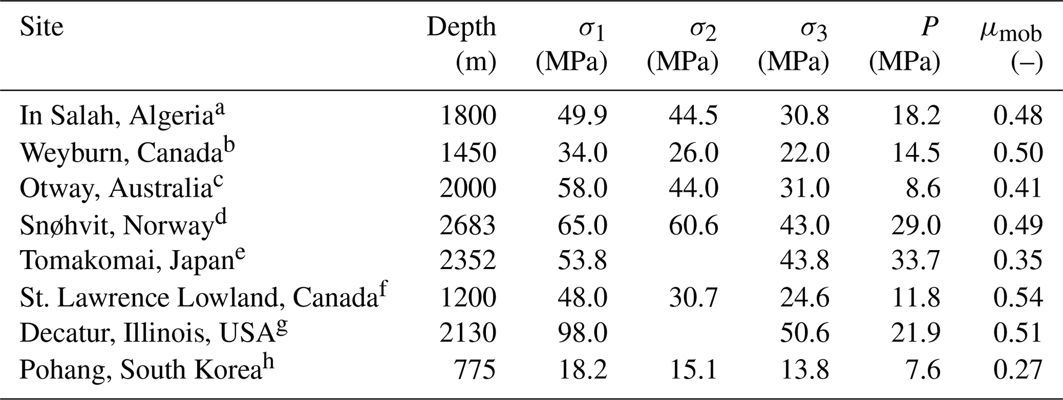
References: a Morris et al. (2011). b White and Johnson (2009). c Nelson et al. (2006), Vidal-Gilbert et al. (2010). d Chiaramonte et al. (2013). e Kano et al. (2013). f Konstantinovskaya et al. (2012). g Bauer et al. (2016). h Lee et al. (2017)
The stress state at each site should be measured in order to determine the maximum sustainable injection pressure and maximum cooling that would lead to a safe CO2 storage (Rutqvist et al., 2007; Kim and Hosseini, 2014). Thus, stress measurements should be routinely performed during wellbore perforation, determining both the magnitude and orientation of the principal stresses (Cornet and Jianmin, 1995). The range of strikes and dips of potentially reactivated faults can be determined once the stress state is known (Morris et al., 1996). This exercise is crucial to identify faults that may induce large seismic events, to foresee an optimal design of the injection strategy and to define mitigation measures (e.g., Birkholzer et al., 2012; Buscheck et al., 2012; Dempsey et al., 2014) if induced seismicity is predicted to possibly occur above a predefined threshold.
The pressure evolution of CO2 injection is favorable to achieve a long-term geomechanically stable situation. In contrast to water injection, which yields a linear increase in pressure with the logarithm of time when a continuous flow rate is injected (Theis, 1935), CO2 leads to a peak at the beginning of injection followed by a relatively constant overpressure (Fig. 3). Thus, pressure evolution is relatively easy to control in CO2 injection operations, which should help to minimize induced (micro)seismicity (Vilarrasa and Carrera, 2015). Such a pressure evolution has been observed in the field, at Ketzin, Germany (Henninges et al., 2011), numerically (e.g., Vilarrasa et al., 2010; Okwen et al., 2011) and analytically (Vilarrasa et al., 2013a).
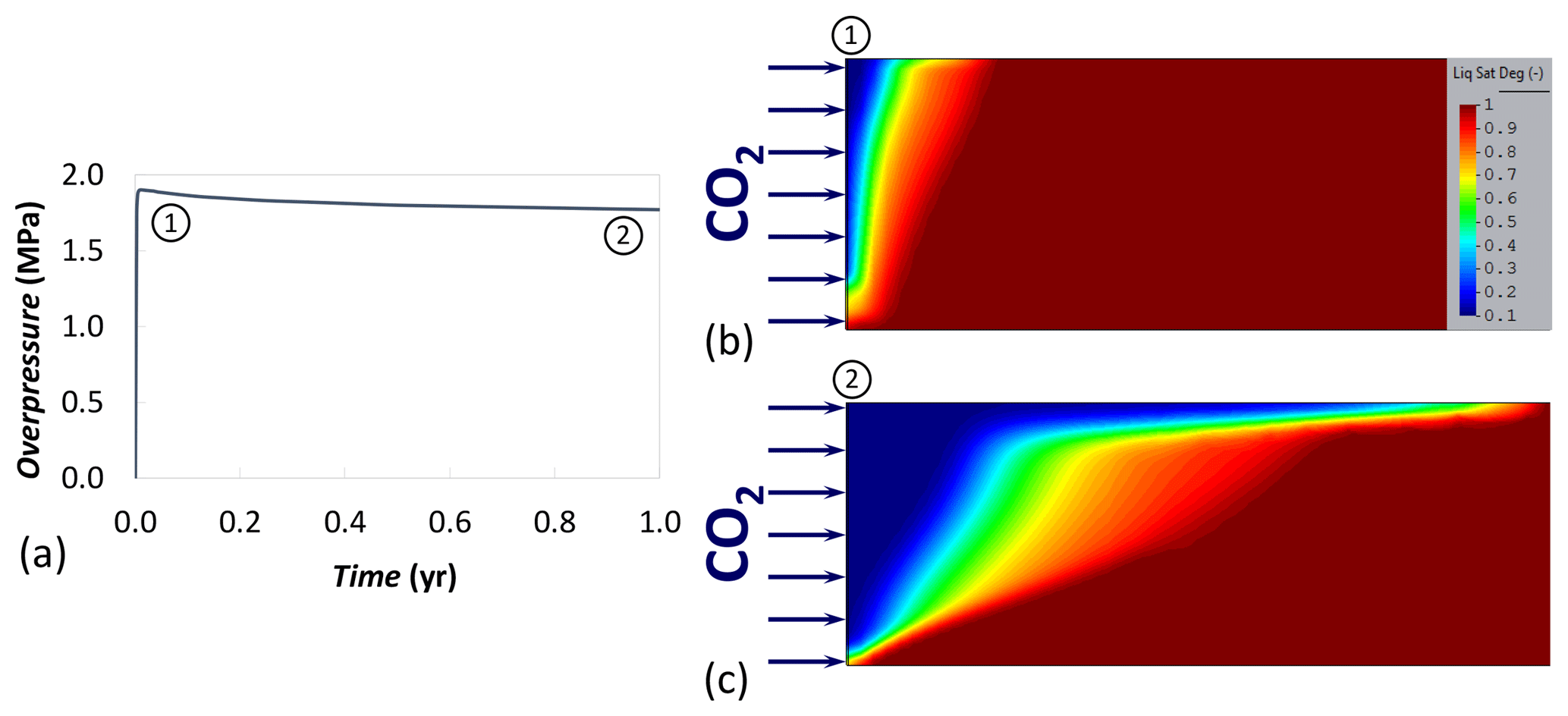
Figure 3(a) CO2 pressure evolution when injecting 1 Mt yr−1 of CO2 through a vertical well in a 100 m thick aquifer with an intrinsic permeability of 10−13 m2 and a radius of 100 km; (b) the CO2 plume shape at the beginning of injection, coinciding with the peak in injection pressure (see number 1 in panel a); and (c) the CO2 plume once gravity override dominates and the capillary fringe has been developed, leading to a slight pressure drop (see number 2 in panel a). The color bar displaying the liquid saturation degree in (b) applies for both (b) and (c).
The initial sharp increase in pore pressure is due not only to viscous forces opposing fluid displacement, but also to capillary forces caused by the desaturation around the injection well, which decreases the relative permeability to both CO2 and water (Fig. 3b). However, once CO2 fills the pores around the injection well (Fig. 3c), the CO2 relative permeability rises. Additionally, since CO2 viscosity is 1 order of magnitude lower than that of brine, CO2 can flow easily inside the storage formation, which leads to a constant or even a slight drop in overpressure (Fig. 3a). This constant evolution of fluid pressure is maintained as long as the pressure perturbation does not reach a boundary. Once a boundary is reached, pressure will decrease in the presence of a constant pressure boundary and will increase in the presence of a low-permeability boundary. The pressure evolution shown in Fig. 3 is not affected by boundary effects because the pressure perturbation does not reach the outer boundary during the displayed injection time. This fluid pressure evolution induces the largest effective stress changes in the caprock at the beginning of injection, coinciding with the peak in pressure increase.
Maintaining the caprock integrity in the long term is favored by two effects that tend to decrease overpressure inside the storage formation: (1) CO2 dissolution into the resident brine and (2) brine flow across the low-permeability formations that confine the storage formation, i.e., caprock and base rock (Vilarrasa and Carrera, 2015). On the one hand, when CO2 dissolves into brine, fluid pressure decreases because the total fluid volume is reduced (Mathias et al., 2011a; Steele-MacInnis et al., 2012). As observed in natural analogues, the percentage of CO2 that may eventually become trapped by dissolution can be as high as 90 % in carbonate storage formations (Gilfillan et al., 2009). In the short term, CO2 dissolution can also be high in storage formations with high vertical permeability ( m2) because of the formation of gravity fingers induced by the unstable situation of having a fluid of a higher density, i.e., CO2-rich brine, above a fluid of lower density, i.e., the resident brine (Riaz et al., 2006; Hidalgo and Carrera, 2009; Pau et al., 2010). On the other hand, caprock permeability at the field scale is 2 to 3 orders of magnitude larger than that at the core scale as a result of the presence of fractures and faults (Neuzil, 1994). Thus, resident brine of the storage formation can flow across the caprock and base rock, lowering the pressure buildup inside the storage formation. Though brine can flow through the caprock because single-phase flow is not hindered by capillarity, CO2 cannot because of the high CO2 entry pressure of clay-rich formations (Benson and Cole, 2008).
To quantify the flow across the caprock in the long term, let us assume a 100 m thick caprock with permeability of 10−18 m2, water viscosity of Pa s (assuming a temperature of 60 ∘C) and a mean overpressure of 1 MPa distributed in a radial distance of 20 km. This scenario yields a flux across the caprock of m s−1 in an area of 1.26×10⁹ m2. Thus, the flow rate across the caprock is 0.031 m3 s−1, which is on the order of magnitude of industrial-scale injection rates (on the order of 0.05 m3 s−1 for annual megatonne injection), effectively lowering the pressure increase inside the storage formation.
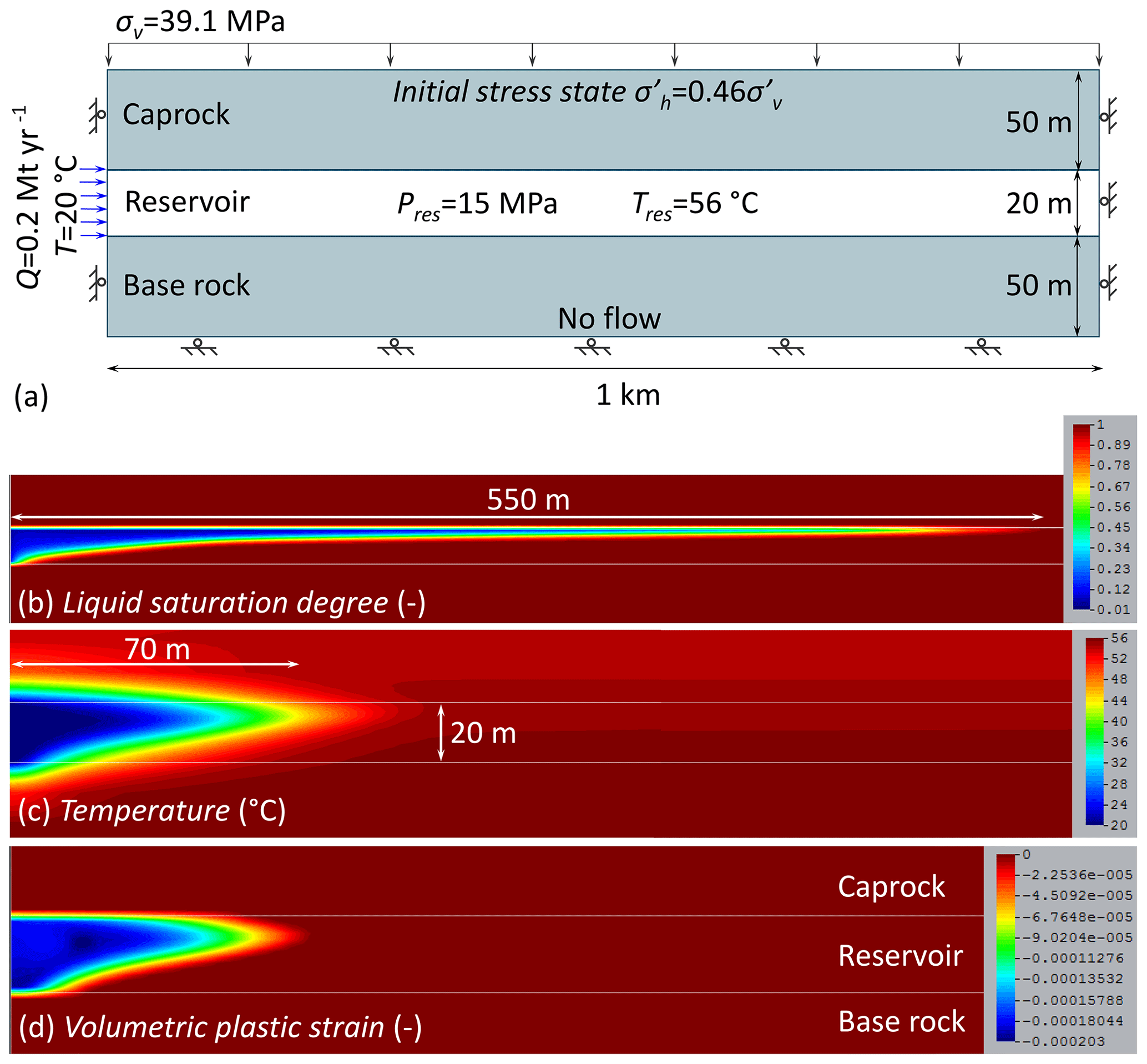
Figure 4(a) Model setup, (b) liquid saturation degree, (c) temperature distribution and (d) volumetric plastic strain after 2 years of injecting 0.2 Mt yr−1 of CO2 at 20 ∘C through a vertical well. While panels (c) and (d) are plotted at the same scale, panel (b) is plotted at a smaller scale.
In addition to pressure increase, thermal effects are also relevant in geologic carbon storage because temperature changes induce thermal stresses that affect fracture stability (Vilarrasa and Rutqvist, 2017). CO2 reaches the bottom of the injection well at a temperature lower than that of the storage formation because CO2 flow within the well is isenthalpic (Pruess, 2006) and thus it heats up at a lower rate than the geothermal gradient (Lu and Connell, 2008). As a result, the rock around injection wells cools down.
To illustrate the effect on fracture stability, we present the simulation results of cold CO2 injection into a deep saline aquifer. Figure 4a displays the model setup with the initial and boundary conditions. The material properties are included in Table A1 in the Appendix. The advance of the cooling front with respect to the CO2 plume is retarded because the rock has to be cooled down (compare Fig. 4b and c) (Bao et al., 2016; LaForce et al., 2015; De Simone et al., 2017a). Cooling mainly advances by advection in the reservoir, but it also extends into the lower portion of the caprock by conduction (Fig. 4c). The extent of the cooling region can become a few hundreds of meters after some decades of CO2 injection at industrial-scale rates, i.e., megatonne injection (Vilarrasa et al., 2014). Thus, unless faults are present in the vicinity of the injection well, they will not be directly affected by cooling. Nevertheless, faults located far from the cooling region may undergo stability changes as a result of the contraction of the cooled rock, which causes changes in far-field stresses (Jeanne et al., 2014).
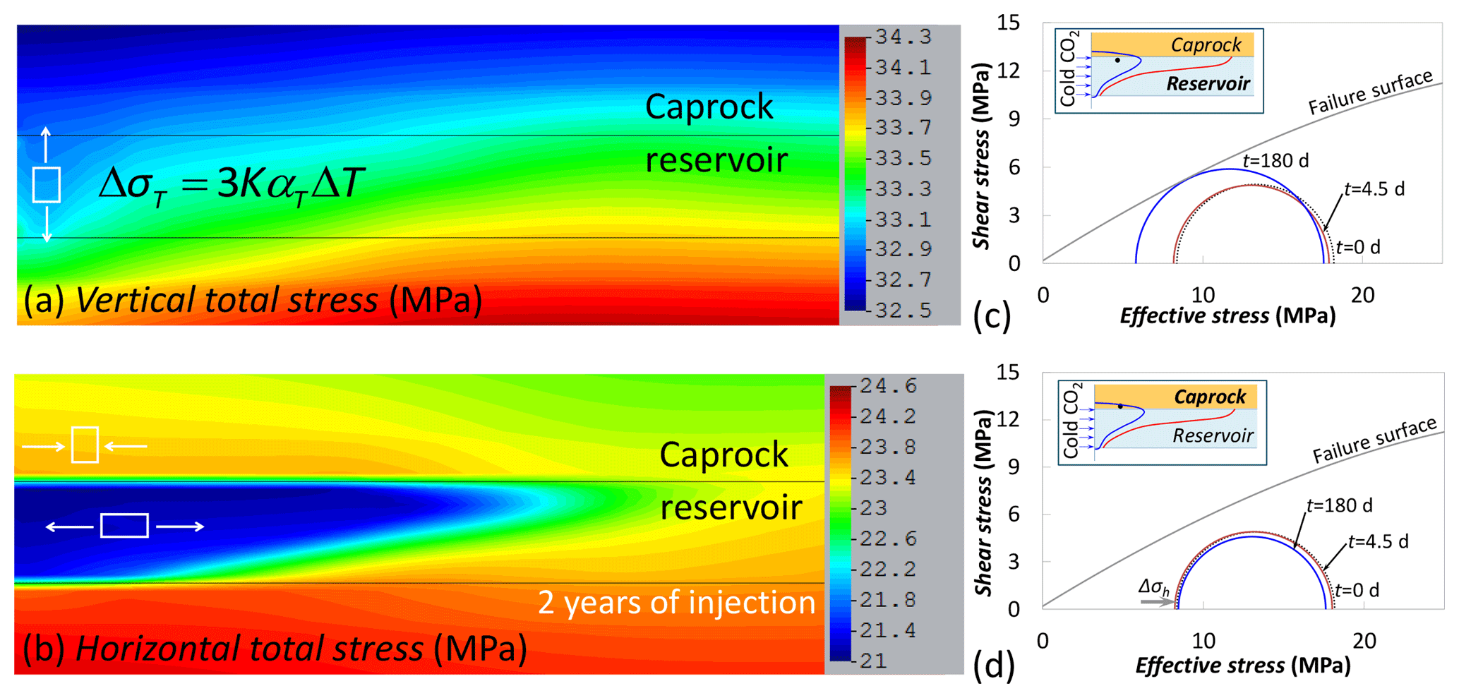
Figure 5Total stresses in the (a) vertical and (b) horizontal direction after 2 years of injecting 0.2 Mt yr−1 of CO2 at 20 ∘C through a vertical well, indicating the sign of the induced stresses. Thermal stresses, ΔσT, are proportional to the bulk modulus, K; the thermal expansion coefficient, αT; and the temperature difference, ΔT. The changes in the Mohr circles at a point placed 25 m away from the injection well in (c) the reservoir (2 m below the reservoir–caprock interface) and (d) the caprock (2 m above the reservoir–caprock interface) are also represented.
The cooling-induced rock contraction and thermal stress reduction shift the stress state towards shear failure conditions and, theoretically, tensile fractures could be formed if the tensile strength were reached (Luo and Bryant, 2010; Goodarzi et al., 2010, 2012; Gor et al., 2013). The temperature-induced stresses are not isotropic (Fig. 5); and thus the effect on fracture stability depends on the stress regime, i.e., normal faulting, strike–slip or reverse faulting (Vilarrasa, 2016). In general, fracture stability becomes more compromised in the reservoir than in the caprock, which may lead to injectivity enhancement while maintaining the caprock sealing capacity (Goodarzi et al., 2015; Vilarrasa et al., 2017c).
This favorable situation occurs especially in normal-faulting stress regimes (Vilarrasa et al., 2013c; Kim and Hosseini, 2015). Figure 5 displays how stress variations induced in the reservoir and caprock as a result of cooling affect fracture stability in a normal-faulting stress regime (i.e., vertical stress larger than horizontal stresses). Both the vertical and horizontal stresses decrease inside the reservoir within the cooled region. The stress reduction is proportional to the rock stiffness, the rock thermal expansion coefficient and the temperature change. The vertical stress reduction within the reservoir causes a disequilibrium in this direction because the overburden on top of the reservoir remains constant so that vertical stresses become smaller than the weight of the material above (Fig. 5a). Thus, to satisfy stress equilibrium and displacement compatibility, an arch effect develops to support the weight of the material above, leading to a reduction of horizontal stresses within the reservoir and an increase in the lower portion of the caprock (Fig. 5b). The net result of these stress changes is to (1) bring the reservoir towards shear failure conditions (the Mohr circles shifts to the left and increases in size, Fig. 5c) and (2) improve stability of the caprock by tightening it (the Mohr circle becomes smaller, Fig. 5d). This contrast in stability between the reservoir and the caprock is highlighted in Fig. 4d, which shows that plastic strain, i.e., strain that occurs because failure conditions have been reached, only takes place in the reservoir and not in the caprock (for details on the failure surface see Vilarrasa and Laloui, 2015).
The situation is slightly different in a reverse-faulting stress regime, where the vertical stress is the minimum principal stress (Vilarrasa, 2016). The cooling-induced increase in horizontal stress in the lower portion of the caprock causes the Mohr circle to increases in size (i.e., the deviatoric stress increases). Nevertheless, this increase is slight because of the high confinement in reverse-faulting stress regimes. Still, shear failure may occur as a result of cooling. Similarly, the deviatoric stress is maintained in a strike–slip stress regime (Vilarrasa, 2016), which may induce shear failure of pre-existing fractures, and thus induced microseismicity, in the cooled region of the caprock, as was likely the case at In Salah, Algeria (Vilarrasa et al., 2015). These results highlight again the importance of characterizing the stress state.
The simulation results shown in Figs. 4 and 5 consider that the thermal expansion coefficient of the storage formation and the caprock are equal. Despite the limited range of the values that the thermal expansion coefficient can take in geomaterials, its magnitude will generally vary between the two formations. Different thermal expansion coefficients between the storage formation and the caprock lead to differential expansion of the rock, building up shear stress in the interface between the two layers. When the thermal expansion coefficient of the caprock is greater than that of the storage formation, deviatoric plastic strain may occur in the lower portion of the caprock as a result of cooling (Vilarrasa and Laloui, 2016). Nonetheless, regardless of the stress regime and the relative values of the thermal expansion coefficient between the storage formation and the caprock, the overall sealing capacity of the caprock is not compromised because only the lower portion of the caprock is affected by cooling and the subsequent stress changes.
Shear slip of faults induces static stress transfer, decreasing stability in some regions – where seismicity rate increases – and increasing stability in others – the so-called stress shadows – where seismicity rate decreases or is even suppressed (Harris and Simpson, 1998). Static stress transfer resulting from induced earthquakes has been found to be relevant for explaining post-injection events in EGS stimulations (Schoenball et al., 2012; De Simone et al., 2017b). The stress transfer causes rotation of the stress tensor, changing the orientation of the faults that are critically oriented to undergo shear failure. Such a change in the orientation of the faults that rupture during water injection and after shut-in was observed at the EGS Basel Deep Heat Mining Project (Deichmann et al., 2014).
Shear slip does not need to be seismic in order to induce stress transfer. Actually, aseismic slip has been reported to indirectly induce seismicity in non-pressurized fault patches (Cappa et al., 2019). The capacity of injection-induced aseismic slip for bringing to failure zones of faults that are not pressurized has been measured in decameter-scale rock laboratories (Guglielmi et al., 2015; Duboeuf et al., 2017). The magnitude of the induced microseismicity in these field experiments is small, on the order of −3.5 (Duboeuf et al., 2017). However, magnitudes may become large in industrial operations if aseismic slip stresses faults below the injection formation. For example, induced earthquakes with a magnitude of up to 5 were triggered close to a geothermal plant at Brawley, California, USA (Wei et al., 2015). The accumulated aseismic slip inducing these earthquakes was estimated to be some 60 cm, nucleating the earthquakes 5 km below the injection formation.
Both seismic and aseismic slip induce stress transfer that affects fracture and fault stability and may induce (micro)seismicity. This effect has been widely studied in natural seismicity, but has received relatively little attention in induced seismicity. Nonetheless, recent studies show that it is a non-negligible effect, which is relevant in post-injection seismicity and for explaining induced events in non-pressurized regions (De Simone et al., 2017b; Cappa et al., 2019). Thus, even though microseismicity induced by shear slip stress transfer has not been observed to date at geologic carbon storage sites, it should be considered a potential triggering mechanism.
The dissolution of CO2 into the resident brine forms an acidic solution that has the potential of dissolving minerals, which in turn may lead to subsequent precipitation of other minerals (Zhang et al., 2009). The fastest geochemical reactions occur in carbonate rocks and in rocks with carbonate-rich cement (Vilarrasa et al., 2019). Carbonate minerals dissolve when they interact with the acidic CO2-rich brine, leading to porosity and permeability increase (Alam et al., 2014). The porosity increase leads to a reduction in rock stiffness and strength, which has been measured in the laboratory to be on the order of 20 %–30 % (Bemer and Lombard, 2010; Vialle and Vanorio, 2011; Vanorio et al., 2011; Kim et al., 2018). The measured changes become smaller for increasing confining pressure (Vanorio et al., 2011) because the higher the confinement, the lower the porosity and the available reactive surface and, thus, the reaction rate. The reduction in rock stiffness affects the strain and stress induced by CO2 injection and the reduction in strength may cause failure of initially stable fractures and faults (recall Fig. 2), leading to induced microseismicity. Thus, the changes in geomechanical properties of rocks (especially carbonate-rich rocks) as a result of CO2–brine–rock geochemical interactions should be evaluated in the laboratory in order to properly assess the induced microseismicity potential.
Caprocks are also affected to some extent by geochemical reactions. Carbonate and feldspar minerals dissolve in shale, leading to precipitation of other carbonate minerals (Yu et al., 2012). But the overall response of caprocks depends on the rock type. While certain caprocks undergo permeability increase due to interaction with CO2 (Olabode and Radonjic, 2014), others present a self-sealing response to CO2 flow due to porosity decrease (Espinoza and Santamarina, 2012) or fracture clogging (Noiriel et al., 2007). Nevertheless, CO2 is only expected to penetrate a short distance, if any, into the caprock because of its high entry pressure, which prevents upwards CO2 flow (Busch et al., 2008).
For other types of host rock, laboratory studies have shown that geochemically induced changes in the geomechanical properties are in general minor (Rohmer et al., 2016). This minor effect has also been observed in fault gouges that have been exposed to acidic conditions for a long period in natural CO2 reservoirs (Bakker et al., 2016). In summary, there is no evidence to expect significant alteration of geomechanical properties induced by geochemical reactions in general, but (1) the issue should not be abandoned and (2) it should receive special attention and site-specific studies in carbonate-rich rocks.
Faults are present at all scales and have been observed to play a role in CO2 storage projects (e.g., Vidal-Gilbert et al., 2010; Rutqvist, 2012; Castelletto et al., 2013b). To name a few, (i) a fault or fractured rock zone opened as a result of pressure increase at In Salah, Algeria, leading to a double-lobe pattern of uplift on the ground (Vasco et al., 2010; Rinaldi and Rutqvist, 2013); (ii) the storage formation at Snøhvit, Norway, was surrounded by low-permeability faults, which limited its storage capacity (Hansen et al., 2013; Chiaramonte et al., 2015); (iii) the Spanish pilot test site at Hontomín contained several minor faults within a few hundred meters from the injection well (Alcalde et al., 2013, 2014); and (iv) the pilot test site at Heletz, Israel, is placed in an anticline crossed by two faults, confining the storage formation to be a few hundred meters wide (Figueiredo et al., 2015). The nature of these faults, i.e., flow barriers or conduits (Caine et al., 1996), controls the stress changes occurring around the fault and thus fault stability (Vilarrasa et al., 2016). Low-permeability faults may lead to the premature closure of storage sites because of pressure limitations on the storage capacity of the formation (Szulczewski et al., 2012). Actually, if multiple low-permeability faults are present and intersecting each other, they will lead to a compartmentalized reservoir (Castelletto et al., 2013a). In such cases, pressure would increase linearly with time (Zhou et al., 2008; Mathias et al., 2011b), increasing injection costs and eventually leading to fault reactivation, and thus induced seismicity, if injection were maintained (Cappa and Rutqvist, 2011a; Pereira et al., 2014; Rutqvist et al., 2016).
Changes in fault permeability due to its reactivation depend on the type of material. Fault reactivation may enhance fault permeability in hard rocks due to dilatancy by 1 to 2 orders of magnitude (Cappa and Rutqvist, 2011b; Guglielmi et al., 2015). This permeability increase raises the question of whether fault reactivation may lead to CO2 leakage. Such an assessment must be made site specific, taking into account the hydro-mechanical properties of the rock and faults. Nonetheless, in general, faults crossing sequences of reservoirs and caprocks maintain a low permeability, at least, in the sections that cross caprocks as a result of the high clay content of the fault (Takahashi, 2003; Egholm et al., 2008). But more importantly, the CO2 entry pressure of the fault remains high in the caprock sections (Vilarrasa and Makhnenko, 2017), hindering upwards CO2 leakage, as observed in numerical simulations that incorporate fault heterogeneity (Rinaldi et al., 2014). Additionally, the stress state of the upper crust, which is characterized by a critically stressed crystalline basement overlaid by generally noncritically stressed sedimentary rock (recall Sect. 3), favors nucleation of the largest seismic events in the crystalline basement rather than in the sedimentary rock where CO2 is stored. This hypocenter distribution has been observed in the central USA as a result of wastewater injection in the basal aquifer, which is consistent with permeability enhancement below the storage formation but not in the caprock and above, which limits the risk of CO2 leakage (Verdon, 2014).
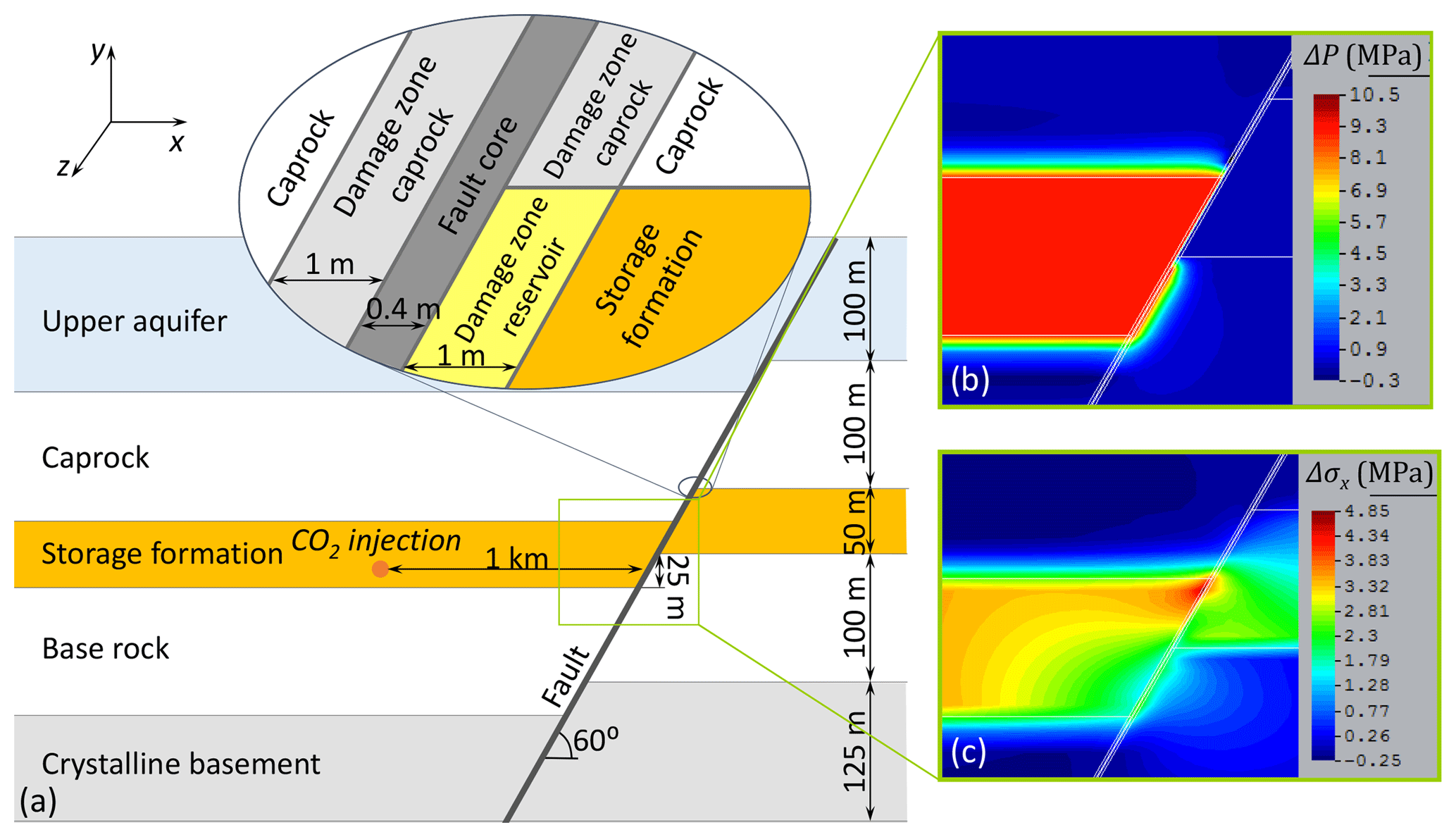
Figure 6(a) Geological setting in a normal-faulting stress regime (plane strain model), including a low-permeability fault that leads to (b) reservoir pressurization, ΔP, and (c) horizontal total stress changes in the in-plane direction, Δσx, when CO2 is injected in the hanging wall at a rate of for 1 year.
Apart from CO2 leakage, the magnitude of potential induced earthquakes is a concern because of the damage and fear that they could generate. The magnitude of earthquakes, M, is proportional to the rock shear modulus, the rupture area and the mean shear slip (Stekettee, 1958). Thus, the magnitude is controlled by the pressurized area of the fault. In this way, the orientation of the injection well affects the magnitude of potential induced seismicity because wells that are parallel to strata pressurize a larger area than vertical wells, but take a longer time to exceed the critical pressure at the fault (Rinaldi et al., 2015). The magnitude of induced seismic events is also controlled by the brittleness of the fault. While brittle faults with a slip-weakening behavior can induce large earthquakes (M>4) (Rutqvist et al., 2016), ductile faults give rise to progressive ruptures in which shear slip progressively accumulates, giving rise to aseismic slip or a swarm-like seismic activity (Vilarrasa et al., 2017b).
Another aspect that controls fault stability as a result of fluid injection is fault offset. Figure 6a represents a typical scenario that can be encountered in a normal-faulting stress regime setting, i.e., a steep fault in which the hanging wall has slid downwards with respect to the footwall. The fault is considered to have an offset equal to half of the storage formation thickness and consists of a low-permeability core (10−19 m2) and damage zones on the core sides. Properties of the damage zone depend on the material it is in contact with, becoming more permeable and less stiff than the intact rock as a result of fracturing (Table A2). Thus, the damage zone is of high permeability next to the storage formation, but of relatively low permeability and high entry pressure next to the caprock and base rock. The caprock and base rock are more deformable than the storage formation (Table A3). The model is plane strain, with a constant vertical stress equal to 29.3 MPa acting on the top boundary and no displacement perpendicular to the other boundaries. The top of the storage formation in the hanging wall is placed at 1.5 km depth. CO2 is injected at a constant mass flow rate of in the hanging wall, 1 km away from the fault, which leads to the pressurization of the storage formation.
Pressure in the hanging wall of the storage formation, where CO2 is being injected, increases by up to 10 MPa after 1 year of injection (Fig. 6b). The low-permeability fault core acts as a flow barrier, causing a rapid reservoir pressurization. This pressure increase expands the storage formation, pushing the fault towards the right-hand side. While pressurization is quite uniform across the storage formation, the resistance to displacement on the other side of the fault depends on the stiffness of the rock. Since the storage formation is stiffer than the base rock, it absorbs larger stresses. As a result, the induced horizontal stresses in the in-plane direction are high where the storage formation is present on both sides of the fault, but it is low where the base rock is on the other side of the fault (Fig. 6c).

Figure 7Distribution of stability changes induced by the pressure and stress changes shown in Fig. 6, measured in terms of the mobilized friction angle changes, Δϕmob. The inset shows the Mohr circles before and after reservoir pressurization.
These stress changes have a direct implication on fault stability. Figure 7 displays the changes in the mobilized friction angle around the fault as a result of CO2 injection. The most destabilized region is the lower half of the pressurized storage formation. Thus, an induced microseismic event would be initiated in that region of the fault, but slip would be arrested below the caprock because fault stability improves within the damage zone of the storage formation on the side that is not pressurized. Thus, induced large-magnitude events are unlikely in geological settings comparable to this simulated scenario. This difference in fault stability can be easily appreciated by representing Mohr circles in these zones (see inset in Fig. 7). Mohr circles shift to the left, getting close to failure, both at the top and bottom of the storage formation due to overpressure. But, while the deviatoric stress is maintained in the lower portion of the pressurized storage formation because the horizontal stress in the in-plane direction does not increase (see red circle in Fig. 7), the size of the Mohr circle decreases in the upper portion of the pressurized storage formation because of the increase in the horizontal stress in the in-plane direction where the storage formation is placed on both sides of the fault (see green circle in Fig. 7). This fault stability analysis highlights the fact that the accurate assessment of fault stability changes in geologic carbon storage sites completely depend on proper site characterization.
Site characterization has been traditionally considered an activity that should be performed for project design and, therefore, prior to operation. These kinds of characterization tests are limited in time and can only characterize a small volume of rock around the injection well (Niemi et al., 2017). The size of the region affected by injection grows with the square root of time and since geologic carbon storage projects are planned to last several decades, full characterization can only be achieved by considering operation as a continuous characterization, which we deem necessary to reduce uncertainty in predictive models of perceivable seismicity.
To assess whether CO2 injection may induce perceivable seismicity, it is necessary to characterize the geological media in order to build a model of the site. The conceptual model should include the geological layers (at least the caprock, potential secondary caprocks, the storage formation and subjacent layers down to the crystalline basement) and faults. Apart from the geometry, the hydraulic (permeability and porosity), thermal (thermal expansion coefficient, thermal conductivity and heat capacity) and geomechanical (stiffness and strength) properties are required. Additionally, the initial conditions should be determined, i.e., the fluid pressure profile (if pressure is hydrostatic or if there are pressure anomalies), the geothermal gradient, Gutenberg–Richter law and, especially for induced seismicity purposes, the stress state. Determining the magnitude and orientation (and their variability) of the stress tensor is critical because fault stability depends on the orientation of a given fault with respect to the stress tensor (Morris et al., 1996). Hydraulic, thermal and geomechanical properties of each model layer can be measured in the laboratory from core samples or in the field. While laboratory measurements allow a tight control of test conditions, they usually test only the rock matrix and fail to acknowledge scale effects associated with spatial variability of the above properties and the impact of discontinuities (e.g., Sanchez-Vila et al., 1996; Ledesma et al., 1996; Zhang et al., 2006; Cai et al., 2007). Thus, interpretation of field tests leads to parameters that are more representative of operation conditions than laboratory experiments.
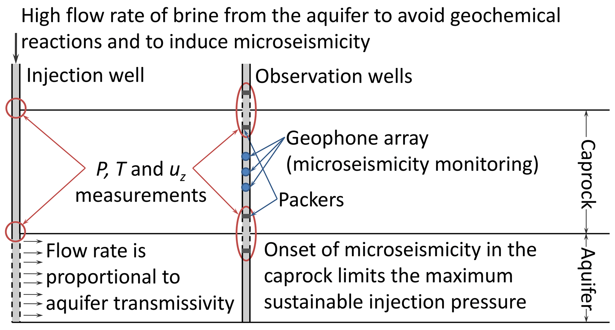
Figure 8Hydro-mechanical characterization test proposed by Vilarrasa et al. (2013b) to quantify the rock properties at the field scale and obtain an initial estimate of the maximum sustainable injection pressure. P refers to pressure, T to temperature and uz to vertical displacement.
To obtain estimates representative at the field scale of the hydraulic and geomechanical properties, Vilarrasa et al. (2013b) proposed a hydro-mechanical characterization test for CO2 storage sites (Fig. 8). The test consists in injecting water at a high flow rate until microseismic events are induced. Ideally, the same brine from the storage formation should be injected to avoid geochemical reactions around the injection well that may alter rock properties. However, injecting brine would imply having a large facility on the surface to store the brine from the storage formation that would have been pumped previously. The test has to be closely monitored with pressure, temperature, deformation and microseismicity monitoring. The hydraulic properties of the storage formation and caprock can be determined from the interpretation of injection as a hydraulic test (Cooper and Jacob, 1946; Hantush, 1956). If heterogeneities are present in the storage formation, their effect is only detectable for a limited period of time (Wheatcraft and Winterberg, 1985; Butler and Liu, 1993). For this reason, it is extremely important to continuously measure pore pressure changes during injection. As for the geomechanical properties of the storage formation and caprock, they can be derived from the interpretation of the vertical displacement at the top of the storage formation and the caprock. Additionally, measuring the pressure evolution in the caprock, which undergoes a pressure drop in response of the pressure buildup in the storage formation (Hsieh, 1996), also gives information on the geomechanical properties. The magnitude of this reverse-water-level fluctuation is inversely proportional to the storage formation stiffness (Vilarrasa et al., 2013b). Injection should be maintained until microseismic events are induced in the caprock, which gives an initial estimate of the maximum sustainable injection pressure that should not be exceeded during CO2 injection to avoid compromising the caprock sealing capacity. This test is valuable to characterize storage sites at a pre-operation stage; but it should be complemented by a continuous site characterization during operation to characterize geological features present in the far field and reduce subsurface uncertainty.
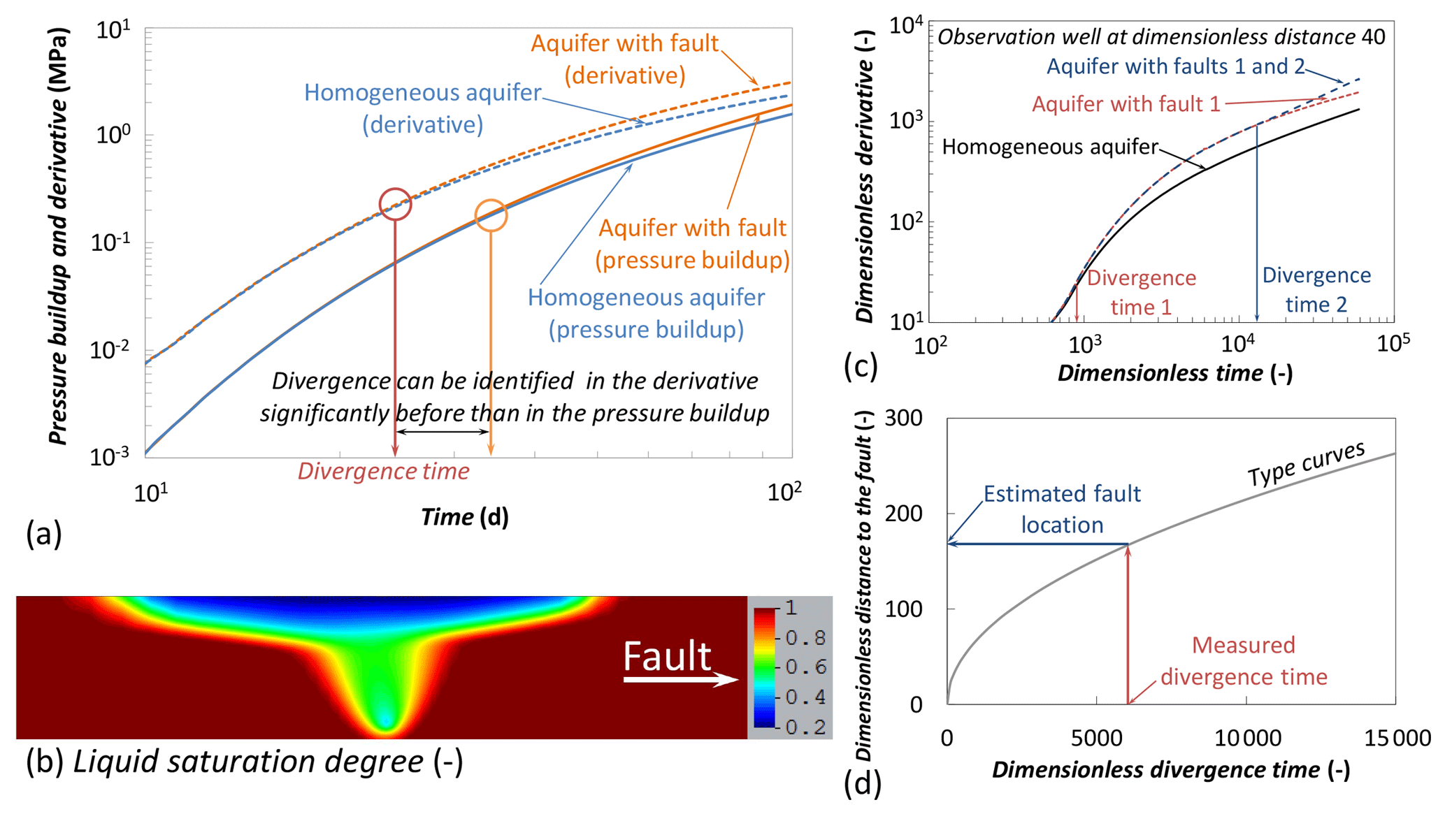
Figure 9(a) Concept of the continuous characterization technique proposed by Vilarrasa et al. (2017a) to detect and locate low-permeability faults using diagnostic plots; (b) asymmetric CO2 plume as a result of the additional pressurization caused by a low-permeability fault, which displaces CO2 towards the opposite direction of the fault; (c) detection of multiple faults by updating the conceptual model of the site and comparing field measurements with predictive simulations; and (d) estimation of the fault location from the measured divergence time in the derivative of the pressure evolution using type curves.
An example of a continuous characterization technique that permits detecting and locating low-permeability faults is that proposed by Vilarrasa et al. (2017a). The idea is to use diagnostic plots, i.e., plots that include the fluid pressure evolution together with the derivative of the fluid pressure with respect to the logarithm of time (Bourdet et al., 1983; Renard et al., 2009), to detect faults significantly before (on the order of days) than if only fluid pressure evolution interpretation would be used (Fig. 9a). This early identification of faults should permit decision makers to perform pressure management if necessary to mitigate future induced seismicity. This methodology only detects faults that are at least 3 orders of magnitude less permeable than the storage formation. However, this should not be a problem in terms of induced seismicity because faults that do not act as a flow barrier induce relatively small changes in fault stability (Vilarrasa et al., 2016). Low-permeability faults generate an additional pressure increase that differs from the expected pressure evolution in an aquifer that would not contain that fault. Thus, by comparing the measured pressure evolution, and its derivative with respect to the logarithm of time, with the predicted one, low-permeability faults can be detected. This additional pressurization also affects the CO2 dynamics because CO2 is pushed away from the direction of the fault, leading to an asymmetric CO2 plume (Fig. 9b). Such asymmetry could be detected at monitoring wells, suggesting the presence of a low-permeability fault, but it could also be due to reservoir heterogeneity (Chen et al., 2014). Once a fault is detected and located from the interpretation of pressure evolution (Fig. 9c and d), it should be incorporated into the conceptual model of the site. Additional characterization techniques may be necessary to obtain precise information on the detected faults. Then, field measurements should be compared with the updated conceptual model, which will permit identifying and locating new faults (Fig. 9c) from the determination of the divergence time and the use of type curves (Fig. 9d).
These characterization techniques entail a number of challenges. To begin with, the drilling of a network of monitoring wells is not yet common practice. Additionally, monitoring techniques also present challenges. Pressure is usually measured at the well head, but calculating the bottom-hole pressure from the well-head pressure is not straightforward given the nonlinearities of the injected fluid, especially for CO2 injection (e.g., Lu and Connell, 2014). Unfortunately, pressure measurements in wells different than the injection well are almost inexistent. Temperature measurements receive even less attention because thermal effects are usually neglected. As for deformation measurements, the ground surface can be measured with InSAR (interferometric synthetic aperture radar) data; but for characterization tests that last a few days, the deformation of the ground may not be detectable given the great depths of suitable storage formations. Thus, deformation should be measured at depth within the boreholes. These measurements pose the question of whether the measured deformation refers to that of the rock or to that of the well. Since the casing of wells is stiffer than rock, the rock may deform more than the well and sliding could even occur between the rock and the cement surrounding the well casing, making accurate measurements difficult. Fiber optics may solve part of these monitoring challenges, but the way this monitoring should be performed is still not crystal clear for the moment. As far as microseismicity monitoring is concerned, arrays of geophones should be placed at depth. Otherwise, the signal-to-noise ratio is too high, which complicates detecting microseismic events. Additionally, multi-sensor arrays with a wide aperture coverage are necessary to accurately locate the events. Despite the existing challenges, such continuous characterization techniques are needed in order to minimize the risk of inducing seismicity in geologic carbon storage projects.
The issues discussed in the previous sections make it apparent that it is possible to effectively minimize the risk of inducing earthquakes that are sufficiently large to be felt on the ground surface and may damage structures. We propose here a workflow consisting of the following steps:
-
performing a detailed initial site characterization, with special emphasis on the geological formations relevant to the site (at least of the storage formation, the caprock, base rock and faults), including the determination of
- –
geomechanical properties (Young's modulus, Poisson ratio, cohesion and friction angle);
- –
hydraulic properties (permeability and porosity);
- –
thermal properties (thermal expansion coefficient, thermal conductivity and heat capacity);
- –
the seismic velocities vp and vs from the surface to the crystalline basement. An accurate determination of these velocities is important not only for proper interpretation of geophysics, but also to locate the hypocenters of the induced seismicity with precision;
- –
the baseline of natural seismicity to establish the initial a and b values of the Gutenberg–Richter law in order to distinguish induced from natural seismicity;
- –
the initial pressure, temperature and stress profiles with depth from the surface to the crystalline basement. The determination of the stress state is particularly important to perform a fault stability analysis of the identified faults and determine the strike and dip of critically oriented faults;
- –
characteristics of geological formations and faults and their location and orientation through 3-D seismic data;
- –
-
putting in place proper monitoring for performing continuous characterization, including
- –
an array of geophones at depth to measure and locate induced microseismicity;
- –
a network of geophones on the surface or in shallow wells with adequate spatial distribution, covering the whole footprint of the storage site to accurately locate induced seismicity. Induced events should be located in quasi-real-time, together with their focal mechanisms, to detect potentially unidentified faults that may induce large earthquakes. Inversion of the stress tensor is also important to detect possible local rotations of the stress tensor (Martínez-Garzón et al., 2013, 2014), which could be induced by pressure increase, cooling and/or shear slip stress transfer (De Simone et al., 2017b). This continuous seismic characterization is particularly important when CO2 is injected in the basal aquifer (Verdon, 2014; Will et al., 2016);
- –
monitoring wells measuring pressure, temperature and CO2 saturation in the storage formation, caprock and secondary aquifer above the storage formation. Monitoring in secondary aquifers is useful for detecting brine and CO2 leakage (e.g., Chabora and Benson, 2009; Zeidouni et al., 2014). Pressure measurements are necessary for continuous characterization techniques as the one described in Sect. 9;
- –
-
carrying out pressure management
- –
storage alternatives to the conventional concept of storing CO2 in deep saline aquifers may be used to have a better control on pressure increase. For example, injection of CO2 dissolved in brine is achieved by creating dipoles of wells in which brine is extracted from the storage formation and reinjected together with CO2 in the same formation (Burton and Bryant, 2009; Jain and Bryant, 2011; Pool et al., 2013). The dipoles of wells limit pressure increase and allow operators to have a better control on it. Similarly, geothermal energy production using CO2 as a working fluid permits lowering pressure increase and additionally extracts geothermal energy (Randolph and Saar, 2011). Despite the promising potential of this technology, the only pilot site that has tried using CO2 as a working fluid yielded a low performance because the thermosyphon that should permit circulating CO2 with a negligible energy consumption did not develop properly (Freifeld et al., 2016). Nevertheless, future research should enable a successful deployment of this technology;
- –
in any case, predictive models of induced seismicity that consider coupled thermo–hydro–mechanical (THM) processes should be applied to identify the injection scenario that minimizes future induced seismicity. These predictive models should be based on THM monitoring and continuous characterization. Continuous characterization will permit updating of the fault stability analysis by incorporating newly detected faults (recall Fig. 9). The range (taking into account the uncertainty in fault properties) of pressure increase that makes faults become critically stressed for shear failure can be determined from the initial stress state, the strike and dip of faults, and the stress changes induced by CO2 injection. Pressure management should be applied to avoid exceeding hazardous levels of pressure increase around faults. To limit pressure, the injection rate may need to be lowered or pressure may need to be released in the vicinity of critically oriented faults (Birkholzer et al., 2012).
- –
Geologic carbon storage can successfully store gigatonnes of CO2 at a low level of induced seismicity provided that proper site characterization, monitoring and pressure management are performed. There are several factors of geologic carbon storage that favor a low induced seismicity risk. First, sedimentary formations where CO2 is planned to be stored are, in general, not critically stressed, which permits generating a certain pressure increase without reaching shear failure conditions. Special care should be taken if CO2 is injected in the basal aquifer, because the crystalline basement is generally critically stressed and may contain unidentified faults that are critically oriented for shear slip. Additionally, CO2 pressure evolution is relatively easy to control because pressure stabilizes after an initial sharp pressure increase, becoming practically constant afterwards. Despite this favorable pressure evolution, if low-permeability faults are present, an additional pressure increase may cause large stress changes around the fault, leading to its reactivation. To prevent this situation, a detailed site characterization – both before the start of operation of projects and continuously during the whole operational stage – monitoring and pressure management should minimize the risk of inducing large (perceivable) earthquakes.
The numerical code that was used to solve the simulations presented in this paper can be downloaded from https://deca.upc.edu/en/projects/code_bright/downloads (last access: 14 June 2019). The required data to reproduce the numerical simulations are provided in the paper and references.
All the presented numerical simulations are performed with the fully coupled finite element code CODE_BRIGHT (Olivella et al., 1994, 1996), which solves non-isothermal two-phase flow in deformable porous media.
Table A1Material properties used in the model of cold CO2 injection shown in Figs. 4 and 5.
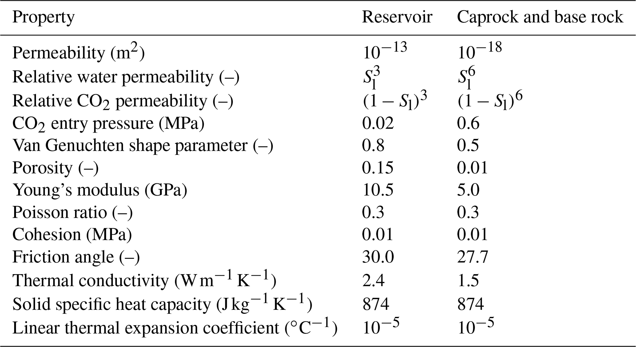
Sl is the liquid saturation degree
Table A2Properties of the materials forming the fault of the model shown in Figs. 6 and 7.
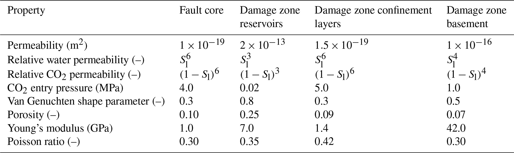
Sl is the liquid saturation degree
Table A3Material properties of the intact rock types included in the model shown in Figs. 6 and 7.
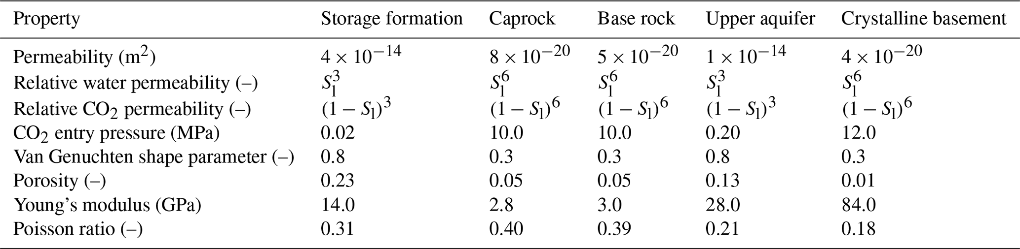
Sl is the liquid saturation degree
VV designed the review, wrote the paper and performed the numerical simulations. All authors contributed to the interpretation of the results and edited the paper.
The authors declare that they have no conflict of interest.
Víctor Vilarrasa acknowledges funding from the European Research Council (ERC) under the European Union's Horizon 2020 Research and Innovation Programme (grant agreement no. 801809). Jonny Rutqvist acknowledges funding by the Assistant Secretary for Fossil Energy, National Energy Technology Laboratory, National Risk Assessment Partnership of the U.S. Department of Energy to the Lawrence Berkeley National Laboratory under contract no. DEAC02-05CH11231.
This research has been supported by the European Research Council (grant no. 801809) and the U.S. Department of Energy, Lawrence Berkeley National Laboratory (grant no. DEAC02-05CH11231).
This paper was edited by Florian Fusseis and reviewed by two anonymous referees.
Alam, M. M., Hjuler, M. L., Christensen, H. F., and Fabricius, I. L.: Petrophysical and rock-mechanics effects of CO2 injection for enhanced oil recovery: Experimental study on chalk from South Arne field, North Sea, J. Petrol. Sci. Eng., 122, 468–487, https://doi.org/10.1016/j.petrol.2014.08.008, 2014.
Alcalde, J., Martí, D., Calahorrano, A., Marzán, I., Ayarza, P., Carbonell, R., Juhlin, C., and Pérez-Estaún, A.: Active seismic characterization experiments of the Hontomín research facility for geological storage of CO2, Spain, Int. J. Greenh. Gas Con., 19, 785–795, https://doi.org/10.1016/j.ijggc.2013.01.039, 2013.
Alcalde, J., Marzán, I., Saura, E., Martí, D., Ayarza, P., Juhlin, C., Pérez-Estaún, A., and Carbonell, R.: 3D geological characterization of the Hontomín CO2 storage site, Spain: Multidisciplinary approach from seismic, well-log and regional data, Tectonophysics, 627, 6–25, https://doi.org/10.1016/j.tecto.2014.04.025, 2014.
Bakker, E., Hangx, S. J., Niemeijer, A. R., and Spiers, C. J.: Frictional behaviour and transport properties of simulated fault gouges derived from a natural CO2 reservoir, Int. J. Greenh. Gas Con., 54, 70–83, https://doi.org/10.1016/j.ijggc.2016.08.029, 2016.
Bao, J., Xu, Z., and Fang, Y.: A coupled thermal-hydro-mechanical simulation for carbon dioxide sequestration, Environ. Geotechnics, 3, 312–324, 2016.
Barton, N.: The shear strength of rock and rock joints, Int. J. Rock Mech. Min., 13, 255–279, https://doi.org/10.1016/0148-9062(76)90003-6, 1976.
Bauer, R. A., Carney, M., and Finley, R. J.: Overview of microseismic response to CO2 injection into the Mt. Simon saline reservoir at the Illinois Basin-Decatur Project, Int. J. Greenh. Gas Con., 54, 378–388, https://doi.org/10.1016/j.ijggc.2015.12.015, 2016.
Bemer, E. and Lombard, J. M.: From injectivity to integrity studies of CO2 geological storage-chemical alteration effects on carbonates petrophysical and geomechanical properties, Oil & Gas Science and Technology – Revue de l'Institut Français du Pétrole, 65, 445–459, https://doi.org/10.2516/ogst/2009028, 2010.
Benson, S. M. and Cole, D. R.: CO2 sequestration in deep sedimentary formations, Elements, 4, 325–331, https://doi.org/10.2113/gselements.4.5.325, 2008.
Birkholzer, J. T., Cihan, A., and Zhou, Q.: Impact-driven pressure management via targeted brine extraction – Conceptual studies of CO2 storage in saline formations, Int. J. Greenh. Gas Con., 7, 168–180, https://doi.org/10.1016/j.ijggc.2012.01.001, 2012.
Bourdet, D., Whittle, T. M., Douglas, A. A., and Pirard, Y. M.: A new set of type curves simplifies well test analysis, World Oil, 196, 95–106, 1983.
Burton, M. and Bryant, S. L.: Surface dissolution: minimizing groundwater impact and leakage risk simultaneously, Energy Procedia, 1, 3707–3714, https://doi.org/10.1016/j.egypro.2009.02.169, 2009.
Busch, A., Alles, S., Gensterblum, Y., Prinz, D., Dewhurst, D. N., Raven, M. D., Stanjek, H., and Krooss, B. M.: Carbon dioxide storage potential of shales, Int. J. Greenh. Gas Con., 2, 297–308, https://doi.org/10.1016/j.ijggc.2008.03.003, 2008.
Buscheck, T. A., Sun, Y., Chen, M., Hao, Y., Wolery, T. J., Bourcier, W. L., Court, B., Celia, M.A., Friedman, J., and Aines, R. D.: Active CO2 reservoir management for carbon storage: Analysis of operational strategies to relieve pressure buildup and improve injectivity, Int. J. Greenh. Gas Con., 6, 230–245, https://doi.org/10.1016/j.ijggc.2011.11.007, 2012.
Butler, J. J. and Liu, W.: Pumping tests in nonuniform aquifers: The radially asymmetric case, Water Resour. Res., 29, 259–269, https://doi.org/10.1029/92WR02128, 1993.
Cai, M., Morioka, H., Kaiser, P. K., Tasaka, Y., Kurose, H., Minami, M., and Maejima, T.: Back-analysis of rock mass strength parameters using AE monitoring data, Int. J. Rock Mech. Min., 44, 538–549, https://doi.org/10.1016/j.ijrmms.2006.09.012, 2007.
Caine, J. S., Evans, J. P., and Forster, C. B.: Fault zone architecture and permeability structure, Geology, 24, 1025–1028, https://doi.org/10.1130/0091-7613(1996)024<1025:FZAAPS>2.3.CO;2, 1996.
Cappa, F. and Rutqvist, J.: Impact of CO2 geological sequestration on the nucleation of earthquakes, Geophys. Res. Lett., 38, L17313, https://doi.org/10.1029/2011GL048487, 2011a.
Cappa, F. and Rutqvist, J.: Modeling of coupled deformation and permeability evolution during fault reactivation induced by deep underground injection of CO2, Int. J. Greenh. Gas Con., 5, 336–346, https://doi.org/10.1016/j.ijggc.2010.08.005, 2011b.
Cappa, F., Scuderi, M. M., Collettini, C., Guglielmi, Y., and Avouac, J. P.: Stabilization of fault slip by fluid injection in the laboratory and in situ, Sci. Adv., 5, eaau4065, https://doi.org/10.1126/sciadv.aau4065, 2019.
Castelletto, N., Gambolati, G., and Teatini, P.: Geological CO2 sequestration in multi-compartment reservoirs: Geomechanical challenges, J. Geophys. Res.-Sol. Ea., 118, 2417–2428, https://doi.org/10.1002/jgrb.50180, 2013a.
Castelletto, N., Teatini, P., Gambolati, G., Bossie-Codreanu, D., Vincké, O., Daniel, J. M., Battistelli, A., Marcolini, M., Donde, F., and Volpi, V.: Multiphysics modeling of CO2 sequestration in a faulted saline formation in Italy, Adv. Water Resour., 62, 570–587, https://doi.org/10.1016/j.advwatres.2013.04.006, 2013b.
Celia, M. A.: Geological storage of captured carbon dioxide as a large-scale carbon mitigation option, Water Resour. Res., 53, 3527–3533, https://doi.org/10.1002/2017WR020841, 2017.
Cesca, S., Grigoli, F., Heimann, S., González, A., Buforn, E., Maghsoudi, S., Blancg, E., and Dahm, T.: The 2013 September–October seismic sequence offshore Spain: a case of seismicity triggered by gas injection?, Geophys. J. Int., 198, 941–953, https://doi.org/10.1093/gji/ggu172, 2014.
Chabora, E. R. and Benson, S. M.: Brine displacement and leakage detection using pressure measurements in aquifers overlying CO2 storage reservoirs, Energy Proced., 1, 2405–2412, https://doi.org/10.1016/j.egypro.2009.01.313, 2009.
Chen, F., Wiese, B., Zhou, Q., Kowalsky, M. B., Norden, B., Kempka, T., and Birkholzer, J. T.: Numerical modeling of the pumping tests at the Ketzin pilot site for CO2 injection: Model calibration and heterogeneity effects, Int. J. Greenh. Gas Con., 22, 200–212, https://doi.org/10.1016/j.ijggc.2014.01.003, 2014.
Chiaramonte, L., White, J. A., Hao, Y., and Ringrose, P.: Probabilistic Risk Assessment of Mechanical Deformation due to CO2 Injection in a Compartmentalized Reservoir, in: 47th US Rock Mechanics/Geomechanics Symposium, American Rock Mechanics Association, San Francisco, CA, USA, 2013.
Chiaramonte, L., White, J. A., and Trainor-Guitton, W.: Probabilistic geomechanical analysis of compartmentalization at the Snøhvit CO2 sequestration project, J. Geophys. Res.-Sol. Ea., 120, 1195–1209, https://doi.org/10.1002/2014JB011376, 2015.
Clarke, H., Eisner, L., Styles, P., and Turner, P.: Felt seismicity associated with shale gas hydraulic fracturing: The first documented example in Europe, Geophys. Res. Lett., 41, 8308–8314, https://doi.org/10.1002/2014GL062047, 2014.
Cooper, H. H. and Jacob, C. E.: A generalized graphical method for evaluating formation constants and summarizing well-field history, Eos, Transactions American Geophysical Union, 27, 526–534, https://doi.org/10.1029/TR027i004p00526, 1946.
Cornet, F. H. and Jianmin, Y.: Analysis of induced seismicity for stress field determination and pore pressure mapping, in: Mechanics Problems in Geodynamics Part I, Birkhäuser, Basel, 677–700, https://doi.org/10.1007/978-3-0348-9065-6_16, 1995.
Cornet, F. H., Helm, J., Poitrenaud, H., and Etchecopar, A.: Seismic and Aseismic Slips Induced by Large-scale Fluid Injections, in: Seismicity Associated with Mines, Reservoirs and Fluid Injections, edited by: Talebi, S., Pageoph Topical Volumes, Birkhäuser, Basel, https://doi.org/10.1007/978-3-0348-8814-1_12, 1997.
Deichmann, N. and Giardini, D.: Earthquakes induced by the stimulation of an enhanced geothermal system below Basel (Switzerland), Seismol. Res. Lett., 80, 784–798, https://doi.org/10.1785/gssrl.80.5.784 , 2009.
Deichmann, N., Kraft, T., and Evans, K. F.: Identification of faults activated during the stimulation of the Basel geothermal project from cluster analysis and focal mechanisms of the larger magnitude events, Geothermics, 52, 84–97, https://doi.org/10.1016/j.geothermics.2014.04.001, 2014.
Dempsey, D., Kelkar, S., and Pawar, R.: Passive injection: A strategy for mitigating reservoir pressurization, induced seismicity and brine migration in geologic CO2 storage, Int. J. Greenh. Gas Con., 28, 96–113, https://doi.org/10.1016/j.ijggc.2014.06.002, 2014.
De Simone, S., Carrera, J., and Gómez-Castro, B. M.: A practical solution to the mechanical perturbations induced by non-isothermal injection into a permeable medium, Int. J. Rock Mech. Min., 91, 7–17, https://doi.org/10.1016/j.ijrmms.2016.11.001, 2017a.
De Simone, S., Carrera, J., and Vilarrasa, V.: Superposition approach to understand triggering mechanisms of post-injection induced seismicity, Geothermics, 70, 85–97, https://doi.org/10.1016/j.geothermics.2017.05.011, 2017b.
Diehl, T., Kraft, T., Kissling, E., and Wiemer, S.: The induced earthquake sequence related to the St. Gallen deep geothermal project (Switzerland): Fault reactivation and fluid interactions imaged by microseismicity, J. Geophys. Res.-Sol. Ea., 122, 7272–7290, https://doi.org/10.1002/2017JB014473, 2017.
Duboeuf, L., De Barros, L., Cappa, F., Guglielmi, Y., Deschamps, A., and Seguy, S.: Aseismic motions drive a sparse seismicity during fluid injections into a fractured zone in a carbonate reservoir, J. Geophys. Res.-Sol. Ea., 122, 8285–8304, https://doi.org/10.1002/2017JB014535, 2017.
Edwards, B., Kraft, T., Cauzzi, C., Kästli, P., and Wiemer, S.: Seismic monitoring and analysis of deep geothermal projects in St Gallen and Basel, Switzerland, Geophys. J. Int., 201, 1022–1039, https://doi.org/10.1093/gji/ggv059, 2015.
Egholm, D. L., Clausen, O. R., Sandiford, M., Kristensen, M. B., and Korstgård, J. A.: The mechanics of clay smearing along faults, Geology, 36, 787–790, https://doi.org/10.1130/G24975A.1 , 2008.
Ellsworth, W. L.: Injection-induced earthquakes, Science, 341, 1225942, https://doi.org/10.1126/science.1225942, 2013.
Espinoza, D. N. and Santamarina, J. C.: Clay interaction with liquid and supercritical CO2: The relevance of electrical and capillary forces, Int. J. Greenh. Gas Con., 10, 351–362, https://doi.org/10.1016/j.ijggc.2012.06.020, 2012.
Evans, K. F., Moriya, H., Niitsuma, H., Jones, R. H., Phillips, W. S., Genter, A., Sausse, J., Jung, R., and Baria, R.: Microseismicity and permeability enhancement of hydrogeologic structures during massive fluid injections into granite at 3 km depth at the Soultz HDR site, Geophys. J. Int., 160, 388–412, https://doi.org/10.1111/j.1365-246X.2004.02474.x, 2005.
Faulkner, D. R., Mitchell, T. M., Healy, D., and Heap, M. J.: Slip on `weak' faults by the rotation of regional stress in the fracture damage zone, Nature, 444, 922–925, https://doi.org/10.1038/nature05353, 2006.
Figueiredo, B., Tsang, C. F., Rutqvist, J., Bensabat, J., and Niemi, A.: Coupled hydro-mechanical processes and fault reactivation induced by CO2 injection in a three-layer storage formation, Int. J. Greenh. Gas Con., 39, 432–448, https://doi.org/10.1016/j.ijggc.2015.06.008, 2015.
Freifeld, B. M., Pan, L., Doughty, C., Zakem, S., Hart, K., and Hostler, S.: Demonstration of Geothermal Energy Production Using Carbon Dioxide as a Working Fluid at the SECARB Cranfield Site, Cranfield, Mississippi, in: Proceedings of the forty-first workshop on geothermal reservoir engineering, Stanford University, Stanford, 2016.
Gaite, B., Ugalde, A., Villaseñor, A., and Blanch, E.: Improving the location of induced earthquakes associated with an underground gas storage in the Gulf of Valencia (Spain), Phys. Earth Planet. In., 254, 46–59, https://doi.org/10.1016/j.pepi.2016.03.006, 2016.
Gilfillan, S. M., Lollar, B. S., Holland, G., Blagburn, D., Stevens, S., Schoell, M., Cassidy, M., Ding, Z., Zhou, Z., Lacrampe-Couloume, G., and Ballentine, C. J.: Solubility trapping in formation water as dominant CO2 sink in natural gas fields, Nature, 458, 614, https://doi.org/10.1038/nature07852, 2009.
Goodarzi, S., Settari, A., Zoback, M. D., and Keith, D.: Thermal aspects of geomechanics and induced fracturing in CO2 injection with application to CO2 sequestration in Ohio River Valley, in: SPE International Conference on CO2 Capture, Storage, and Utilization, Society of Petroleum Engineers, New Orleans, Louisiana, USA, https://doi.org/10.2118/139706-MS, 2010.
Goodarzi, S., Settari, A., and Keith, D.: Geomechanical modeling for CO2 storage in Nisku aquifer in Wabamun Lake area in Canada, Int. J. Greenh. Gas Con., 10, 113–122, https://doi.org/10.1016/j.ijggc.2012.05.020, 2012.
Goodarzi, S., Settari, A., Zoback, M. D., and Keith, D. W.: Optimization of a CO2 storage project based on thermal, geomechanical and induced fracturing effects, J. Petrol. Sci. Eng., 134, 49–59, https://doi.org/10.1016/j.petrol.2015.06.004, 2015.
Gor, G. Y., Elliot, T. R., and Prévost, J. H.: Effects of thermal stresses on caprock integrity during CO2 storage, Int. J. Greenh. Gas Con., 12, 300–309, https://doi.org/10.1016/j.ijggc.2012.11.020, 2013.
Grigoli, F., Cesca, S., Priolo, E., Rinaldi, A. P., Clinton, J. F., Stabile, T. A., Dost, B., Garcia Fernandez, M., Wiemer, S., and Dahm, T.: Current challenges in monitoring, discrimination, and management of induced seismicity related to underground industrial activities: A European perspective, Rev. Geophys., 55, 310–340, https://doi.org/10.1002/2016RG000542, 2017.
Grigoli, F., Cesca, S., Rinaldi, A. P., Manconi, A., López-Comino, J. A., Clinton, J. F., Westaway, R., Cauzzi, C., Dahm, T., and Wiemer, S.: The November 2017 Mw 5.5 Pohang earthquake: A possible case of induced seismicity in South Korea, Science, 360, 1003–1006, https://doi.org/10.1126/science.aat2010, 2018.
Guglielmi, Y., Cappa, F., Avouac, J. P., Henry, P., and Elsworth, D.: Seismicity triggered by fluid injection–induced aseismic slip, Science, 348, 1224–1226, https://doi.org/10.1126/science.aab0476, 2015.
Hansen, O., Gilding, D., Nazarian, B., Osdal, B., Ringrose, P., Kristoffersen, J. B., Eiken, O., and Hansen, H.: Snøhvit: The history of injecting and storing 1 Mt CO2 in the fluvial Tubåen Fm, Energy Proced., 37, 3565–3573, https://doi.org/10.1016/j.egypro.2013.06.249, 2013.
Hantush, M. S.: Analysis of data from pumping tests in leaky aquifers, Eos, Transactions American Geophysical Union, 37, 702–714, https://doi.org/10.1029/TR037i006p00702, 1956.
Häring, M. O., Schanz, U., Ladner, F., and Dyer, B. C.: Characterisation of the Basel 1 enhanced geothermal system, Geothermics, 37, 469–495, https://doi.org/10.1016/j.geothermics.2008.06.002, 2008.
Harris, R. A. and Simpson, R. W.: Suppression of large earthquakes by stress shadows: A comparison of Coulomb and rate-and-state failure, J. Geophys. Res.-Sol. Ea., 103, 24439–24451, https://doi.org/10.1029/98JB00793, 1998.
Henninges, J., Liebscher, A., Bannach, A., Brandt, W., Hurter, S., Köhler, S., Möller, F., and CO2SINK Group: PT-ρ and two-phase fluid conditions with inverted density profile in observation wells at the CO2 storage site at Ketzin (Germany), Energy Proced., 4, 6085–6090, https://doi.org/10.1016/j.egypro.2011.02.614, 2011.
Hidalgo, J. J. and Carrera, J.: Effect of dispersion on the onset of convection during CO2 sequestration, J. Fluid Mech., 640, 441-452, https://doi.org/10.1017/S0022112009991480, 2009.
Hitchon, B., Gunter, W. D., Gentzis, T., and Bailey, R. T.: Sedimentary basins and greenhouse gases: a serendipitous association, Energ. Convers. Manage., 40, 825–843, https://doi.org/10.1016/S0196-8904(98)00146-0, 1999.
Hsieh, P. A.: Deformation-induced changes in hydraulic head during ground-water withdrawal, Groundwater, 34, 1082–1089, https://doi.org/10.1111/j.1745-6584.1996.tb02174.x, 1996.
Hsieh, P. A. and Bredehoeft, J. D.: A reservoir analysis of the Denver earthquakes: A case of induced seismicity, J. Geophys. Res.-Sol. Ea., 86, 903–920, https://doi.org/10.1029/JB086iB02p00903, 1981.
IPCC: Special report on Global warming of 1.5 ∘C, Incheon, South Korea, IPCC, 2018.
Jaeger, J. C., Cook, N. G., and Zimmerman, R.: Fundamentals of rock mechanics, John Wiley & Sons, 2009.
Jain, L. and Bryant, S. L.: Optimal design of injection/extraction wells for the surface dissolution CO2 storage strategy, Energy Proced., 4, 4299–4306, https://doi.org/10.1016/j.egypro.2011.02.380, 2011.
Jeanne, P., Rutqvist, J., Dobson, P. F., Walters, M., Hartline, C., and Garcia, J.: The impacts of mechanical stress transfers caused by hydromechanical and thermal processes on fault stability during hydraulic stimulation in a deep geothermal reservoir, Int. J. Rock Mech. Min., 72, 149–163, https://doi.org/10.1016/j.ijrmms.2014.09.005, 2014.
Kano, Y., Funatsu, T., Nakao, S., Kusunose, K., Ishido, T., Lei, X. L., and Tosha, T.: Fault stability analysis related to CO2 injection at Tomakomai, Hokkaido, Japan, Energy Proced., 37, 4946–4953, https://doi.org/10.1016/j.egypro.2013.06.406, 2013.
Kaven, J. O., Hickman, S. H., McGarr, A. F., and Ellsworth, W. L.: Surface monitoring of microseismicity at the Decatur, Illinois, CO2 sequestration demonstration site, Seismol. Res. Lett., 86, 1096–1101, https://doi.org/10.1785/0220150062, 2015.
Kim, K. H., Ree, J. H., Kim, Y., Kim, S., Kang, S. Y., and Seo, W.: Assessing whether the 2017 Mw 5.4 Pohang earthquake in South Korea was an induced event, Science, 360, 1007–1009, https://doi.org/10.1126/science.aat6081, 2018.
Kim, S. and Hosseini, S. A.: Geological CO2 storage: Incorporation of pore-pressure/stress coupling and thermal effects to determine maximum sustainable pressure limit, Energy Proced., 63, 3339–3346, https://doi.org/10.1016/j.egypro.2014.11.362, 2014.
Kim, S. and Hosseini, S. A.: Hydro-thermo-mechanical analysis during injection of cold fluid into a geologic formation, Int. J. Rock Mech. Min., 77, 220–236, https://doi.org/10.1016/j.ijrmms.2015.04.010, 2015.
Kim, K., Vilarrasa, V., and Makhnenko, R.: CO2 injection effect on Geomechanical and flow properties of calcite-rich reservoirs, Fluids, 3, 66, https://doi.org/10.3390/fluids3030066, 2018.
King, G. C., Stein, R. S., and Lin, J.: Static stress changes and the triggering of earthquakes, B. Seismol. Soc. Am., 84, 935–953, 1994.
Konstantinovskaya, E., Malo, M., and Castillo, D. A.: Present-day stress analysis of the St. Lawrence Lowlands sedimentary basin (Canada) and implications for caprock integrity during CO2 injection operations, Tectonophysics, 518, 119–137, https://doi.org/10.1016/j.tecto.2011.11.022, 2012.
LaForce, T., Ennis-King, J., and Paterson, L.: Semi-analytical temperature and stress profiles for nonisothermal CO2 injection, in: Proceedings of the World Geothermal Congress, Melbourne, Australia, 19–25 April 2015.
Ledesma, A., Gens, A., and Alonso, E. E.: Parameter and variance estimation in geotechnical backanalysis using prior information, Int. J. Numer. Anal. Met., 20, 119–141, https://doi.org/10.1002/(SICI)1096-9853(199602)20:2<119::AID-NAG810>3.0.CO;2-L, 1996.
Lee, H., Shinn, Y. J., Ong, S. H., Woo, S. W., Park, K. G., Lee, T. J., and Moon, S. W.: Fault reactivation potential of an offshore CO2 storage site, Pohang Basin, South Korea, J. Petrol. Sci. Eng., 152, 427–442, https://doi.org/10.1016/j.petrol.2017.03.014, 2017.
Lu, M. and Connell, L. D.: Non-isothermal flow of carbon dioxide in injection wells during geological storage, Int. J. Greenh. Gas Con., 2, 248–258, https://doi.org/10.1016/S1750-5836(07)00114-4, 2008.
Lu, M. and Connell, L. D.: The transient behaviour of CO2 flow with phase transition in injection wells during geological storage – Application to a case study, J. Petrol. Sci. Eng., 124, 7–18, https://doi.org/10.1016/j.petrol.2014.09.024, 2014.
Luo, Z. and Bryant, S. L.: Influence of thermo-elastic stress on CO2 injection induced fractures during storage, In SPE International Conference on CO2 capture, storage, and utilization, Society of Petroleum Engineers, New Orleans, Louisiana, USA, https://doi.org/10.2118/139719-MS, 2010.
Martínez-Garzón, P., Bohnhoff, M., Kwiatek, G., and Dresen, G.: Stress tensor changes related to fluid injection at The Geysers geothermal field, California, Geophys. Res. Lett., 40, 2596–2601, https://doi.org/10.1002/grl.50438, 2013.
Martínez-Garzón, P., Kwiatek, G., Ickrath, M., and Bohnhoff, M.: MSATSI: A MATLAB package for stress inversion combining solid classic methodology, a new simplified user-handling, and a visualization tool, Seismol. Res. Lett., 85, 896–904, https://doi.org/10.1785/0220130189, 2014.
Mathias, S. A., Gluyas, J. G., González Martínez de Miguel, G. J., and Hosseini, S. A.: Role of partial miscibility on pressure buildup due to constant rate injection of CO2 into closed and open brine aquifers, Water Resour. Res., 47, W12525, https://doi.org/10.1029/2011WR011051, 2011a.
Mathias, S. A., Gonzalez Martinez de Miguel, G. J., Thatcher, K. E., and Zimmerman, R. W.; Pressure buildup during CO2 injection into a closed brine aquifer, Transport Porous Med., 89, 383–397, https://doi.org/10.1007/s11242-011-9776-z, 2011b.
Morris, A., Ferrill, D. A., and Henderson, D. B.: Slip-tendency analysis and fault reactivation, Geology, 24, 275–278, https://doi.org/10.1130/0091-7613(1996)024<0275:STAAFR>2.3.CO;2, 1996.
Morris, J. P., Hao, Y., Foxall, W., and McNab, W.: A study of injection-induced mechanical deformation at the In Salah CO2 storage project, Int. J. Greenh. Gas Con., 5, 270–280, https://doi.org/10.1016/j.ijggc.2010.10.004, 2011.
Myer, L. R. and Daley, T. M.: Elements of a best practices approach to induced seismicity in geologic storage, Energy Proced., 4, 3707–3713, https://doi.org/10.1016/j.egypro.2011.02.303, 2011.
Nelson, E., Hillis, R., Sandiford, M., Reynolds, S., and Mildren, S.: Present-day state-of-stress of southeast Australia, The APPEA Journal, 46, 283–306, https://doi.org/10.1071/AJ05016, 2006.
Neuzil, C. E.: How permeable are clays and shales?, Water Resour. Res., 30, 145–150, https://doi.org/10.1029/93WR02930, 1994.
Niemi, A., Edlmann, K., Carrera, J., Juhlin, C., Tatomir, A., Ghergut, I., Sauter, M., Bensabat, J., Fagerlund, F., Rasmusson, K., Cornet, F. H., McDermott, C. I., and Vilarrasa, V.: Site Characterization, in: Geological Storage of CO2 in Deep Saline Formations, pp. 309–380, Springer, Dordrecht, https://doi.org/10.1007/978-94-024-0996-3_7, 2017.
Noiriel, C., Madé, B., and Gouze, P.: Impact of coating development on the hydraulic and transport properties in argillaceous limestone fracture, Water Resour. Res., 43, W09406, https://doi.org/10.1029/2006WR005379, 2007.
Okada, Y.: Internal deformation due to shear and tensile faults in a half-space, B. Seismol. Soc. Am., 82, 1018–1040, 1992.
Okwen, R. T., Stewart, M. T., and Cunningham, J. A.: Temporal variations in near-wellbore pressures during CO2 injection in saline aquifers, Int. J. Greenh. Gas Con., 5, 1140–1148, https://doi.org/10.1016/j.ijggc.2011.07.011, 2011.
Olabode, A. and Radonjic, M.: Shale caprock/acidic brine interaction in underground CO2 storage, J. Energ. Resour.-ASME, 136, 042901, https://doi.org/10.1115/1.4027567, 2014.
Oldenburg, C. M.: The risk of induced seismicity: is cap-rock integrity on shaky ground?, Greenh. Gases, 2, 217–218, https://doi.org/10.1002/ghg.1299, 2012.
Olivella, S., Carrera, J., Gens, A., and Alonso, E. E.: Nonisothermal multiphase flow of brine and gas through saline media, Transport Porous Med., 15, 271–293, https://doi.org/10.1007/BF00613282, 1994.
Olivella, S., Gens, A., Carrera, J., and Alonso, E. E.: Numerical formulation for a simulator (CODE_BRIGHT) for the coupled analysis of saline media, Eng. Computations, 13, 87–112, https://doi.org/10.1108/02644409610151575, 1996.
Parotidis, M., Shapiro, S. A., and Rothert, E.: Back front of seismicity induced after termination of borehole fluid injection, Geophys. Res. Lett., 31, L02612, https://doi.org/10.1029/2003GL018987, 2004.
Paterson, L., Lu, M., Connell, L. D., and Ennis-King, J.: Numerical modeling of pressure and temperature profiles including phase transitions in carbon dioxide wells, SPE Annual Technical Conference and Exhibition, Denver, 21–24 September 2008, https://doi.org/10.2118/115946-MS, 2008.
Pau, G. S., Bell, J. B., Pruess, K., Almgren, A. S., Lijewski, M. J., and Zhang, K.: High-resolution simulation and characterization of density-driven flow in CO2 storage in saline aquifers, Adv. Water Resour., 33, 443–455, https://doi.org/10.1016/j.advwatres.2010.01.009, 2010.
Pereira, L. C., Guimarães, L. J., Horowitz, B., and Sánchez, M.: Coupled hydro-mechanical fault reactivation analysis incorporating evidence theory for uncertainty quantification, Comput. Geotech., 56, 202–215, https://doi.org/10.1016/j.compgeo.2013.12.007, 2014.
Pool, M., Carrera, J., Vilarrasa, V., Silva, O., and Ayora, C.: Dynamics and design of systems for geological storage of dissolved CO2, Adv. Water Resour., 62, 533–542, https://doi.org/10.1016/j.advwatres.2013.10.001, 2013.
Pruess, K.: Enhanced geothermal systems (EGS) using CO2 as working fluid – A novel approach for generating renewable energy with simultaneous sequestration of carbon, Geothermics, 35, 351–367, https://doi.org/10.1016/j.geothermics.2006.08.002, 2006.
Randolph, J. B. and Saar, M. O.: Combining geothermal energy capture with geologic carbon dioxide sequestration, Geophys. Res. Lett., 38, L10401, https://doi.org/10.1029/2011GL047265, 2011.
Renard, P., Glenz, D., and Mejias, M.: Understanding diagnostic plots for well-test interpretation, Hydrogeol. J., 17, 589–600, https://doi.org/10.1007/s10040-008-0392-0, 2009.
Riaz, A., Hesse, M., Tchelepi, H. A., and Orr, F. M.: Onset of convection in a gravitationally unstable diffusive boundary layer in porous media, J. Fluid Mech., 548, 87–111, https://doi.org/10.1017/S0022112005007494, 2006.
Rinaldi, A. P. and Rutqvist, J.: Modeling of deep fracture zone opening and transient ground surface uplift at KB-502 CO2 injection well, In Salah, Algeria, Int. J. Greenh. Gas Con., 12, 155–167, https://doi.org/10.1016/j.ijggc.2012.10.017, 2013.
Rinaldi, A. P., Jeanne, P., Rutqvist, J., Cappa, F., and Guglielmi, Y.: Effects of fault-zone architecture on earthquake magnitude and gas leakage related to CO2 injection in a multi-layered sedimentary system, Greenh. Gases, 4, 99–120, https://doi.org/10.1002/ghg.1403, 2014.
Rinaldi, A. P., Vilarrasa, V., Rutqvist, J., and Cappa, F.: Fault reactivation during CO2 sequestration: Effects of well orientation on seismicity and leakage, Greenh. Gases, 5, 645–656, https://doi.org/10.1002/ghg.1511, 2015.
Rohmer, J., Pluymakers, A., and Renard, F.: Mechano-chemical interactions in sedimentary rocks in the context of CO2 storage: Weak acid, weak effects?, Earth-Sci. Rev., 157, 86–110, https://doi.org/10.1016/j.earscirev.2016.03.009, 2016.
Rubinstein, J. L. and Mahani, A. B.: Myths and facts on wastewater injection, hydraulic fracturing, enhanced oil recovery, and induced seismicity, Seismol. Res. Lett., 86, 1060–1067, https://doi.org/10.1785/0220150067 , 2015.
Rutqvist, J.: The geomechanics of CO2 storage in deep sedimentary formations, Geotechnical and Geological Engineering, 30, 525–551, https://doi.org/10.1007/s10706-011-9491-0, 2012.
Rutqvist, J.: Fractured rock stress-permeability relationships from in situ data and effects of temperature and chemical-mechanical couplings, Geofluids, 15, 48–66, https://doi.org/10.1111/gfl.12089, 2015.
Rutqvist, J., Birkholzer, J., Cappa, F., and Tsang, C. F.: Estimating maximum sustainable injection pressure during geological sequestration of CO2 using coupled fluid flow and geomechanical fault-slip analysis, Energy Convers. Manage., 48, 1798–1807, https://doi.org/10.1016/j.enconman.2007.01.021, 2007.
Rutqvist, J., Rinaldi, A. P., Cappa, F., Jeanne, P., Mazzoldi, A., Urpi, L., Guglielmi, Y., and Vilarrasa, V.: Fault activation and induced seismicity in geological carbon storage–Lessons learned from recent modeling studies, J. Rock Mech. Geotech. Eng., 8, 789–804, https://doi.org/10.1016/j.jrmge.2016.09.001, 2016.
Sanchez-Vila, X., Carrera, J., and Girardi, J.: Scale effects in transmissivity, J. Hydrol., 183, 1–22, https://doi.org/10.1016/S0022-1694(96)80031-X, 1996.
Schoenball, M., Baujard, C., Kohl, T., and Dorbath, L.: The role of triggering by static stress transfer during geothermal reservoir stimulation, J. Geophys. Res.-Sol. Ea., 117, https://doi.org/10.1029/2012JB009304, 2012.
Shapiro, S. A., Rothert, E., Rath, V., and Rindschwentner, J.: Characterization of fluid transport properties of reservoirs using induced microseismicity, Geophysics, 67, 212–220, https://doi.org/10.1190/1.1451597, 2002.
Steele-MacInnis, M., Capobianco, R. M., Dilmore, R., Goodman, A., Guthrie, G., Rimstidt, J. D., and Bodnar, R. J.: Volumetrics of CO2 storage in deep saline formations, Environ. Sci. Technol., 47, 79–86, https://doi.org/10.1021/es301598t, 2012.
Steketee, J. A.: On Volterra's dislocations in a semi-infinite elastic medium, Can. J. Phys., 36, 192–205, https://doi.org/10.1139/p58-024, 1958.
Stork, A. L., Verdon, J. P., and Kendall, J. M.: The microseismic response at the In Salah Carbon Capture and Storage (CCS) site, Int. J. Greenh. Gas Con., 32, 159–171, https://doi.org/10.1016/j.ijggc.2014.11.014, 2015.
Streit, J. E. and Hillis, R. R.: Estimating fault stability and sustainable fluid pressures for underground storage of CO2 in porous rock, Energy, 29, 1445–1456, https://doi.org/10.1016/j.energy.2004.03.078, 2004.
Szulczewski, M. L., MacMinn, C. W., Herzog, H. J., and Juanes, R.: Lifetime of carbon capture and storage as a climate-change mitigation technology, P. Natl. Acad. Sci. USA, 109, 5185–5189, https://doi.org/10.1073/pnas.1115347109, 2012.
Takahashi, M.: Permeability change during experimental fault smearing, J. Geophys. Res.-Sol. Ea., 108, 2235, https://doi.org/10.1029/2002JB001984, 2003.
Theis, C. V.: The relation between the lowering of the piezometric surface and the rate and duration of discharge of a well using ground-water storage, Eos, Transactions American Geophysical Union, 16, 519–524, https://doi.org/10.1029/TR016i002p00519, 1935.
Vanorio, T., Nur, A., and Ebert, Y.: Rock physics analysis and time-lapse rock imaging of geochemical effects due to the injection of CO2 into reservoir rocks, Geophysics, 76, O23–O33, https://doi.org/10.1190/geo2010-0390.1, 2011.
Vasco, D. W., Rucci, A., Ferretti, A., Novali, F., Bissell, R. C., Ringrose, P. S., Mathieson, A. S., and Wright, I. W.: Satellite-based measurements of surface deformation reveal fluid flow associated with the geological storage of carbon dioxide, Geophys. Res. Lett., 37, L03303, https://doi.org/10.1029/2009GL041544, 2010.
Verdon, J. P., Kendall, J. M., White, D. J., and Angus, D. A.: Linking microseismic event observations with geomechanical models to minimise the risks of storing CO2 in geological formations, Earth Planet. Sc. Lett., 305, 143–152, https://doi.org/10.1016/j.epsl.2011.02.048, 2011.
Verdon, J. P.: Significance for secure CO2 storage of earthquakes induced by fluid injection, Environ. Res. Lett., 9, 064022, https://doi.org/10.1088/1748-9326/9/6/064022, 2014.
Verdon, J. P., Stork, A. L., Bissell, R. C., Bond, C. E., and Werner, M. J.: Simulation of seismic events induced by CO2 injection at In Salah, Algeria, Earth Planet. Sc. Lett., 426, 118–129, https://doi.org/10.1016/j.epsl.2015.06.029, 2015.
Vialle, S. and Vanorio, T.: Laboratory measurements of elastic properties of carbonate rocks during injection of reactive CO2-saturated water, Geophys. Res. Lett., 38, L01302, https://doi.org/10.1029/2010GL045606, 2011.
Vidal-Gilbert, S., Tenthorey, E., Dewhurst, D., Ennis-King, J., Van Ruth, P., and Hillis, R.: Geomechanical analysis of the Naylor Field, Otway Basin, Australia: Implications for CO2 injection and storage, Int. J. Greenh. Gas Con., 4, 827–839, https://doi.org/10.1016/j.ijggc.2010.06.001, 2010.
Vilarrasa, V.: The role of the stress regime on microseismicity induced by overpressure and cooling in geologic carbon storage, Geofluids, 16, 941–953, https://doi.org/10.1111/gfl.12197, 2016.
Vilarrasa, V. and Carrera, J.: Geologic carbon storage is unlikely to trigger large earthquakes and reactivate faults through which CO2 could leak, P. Natl. Acad. Sci. USA, 112, 5938–5943, https://doi.org/10.1073/pnas.1413284112, 2015.
Vilarrasa, V. and Laloui, L.: Potential fracture propagation into the caprock induced by cold CO2 injection in normal faulting stress regimes, Geomechanics for Energy and the Environment, 2, 22–31, https://doi.org/10.1016/j.gete.2015.05.001, 2015.
Vilarrasa, V. and Laloui, L.: Impacts of thermally induced stresses on fracture stability during geological storage of CO2, Energy Proced., 86, 411–419, https://doi.org/10.1016/j.egypro.2016.01.042, 2016.
Vilarrasa, V. and Makhnenko, R. Y.: Caprock integrity and induced seismicity from laboratory and numerical experiments, Energy Proced., 125, 494–503, https://doi.org/10.1016/j.egypro.2017.08.172, 2017.
Vilarrasa, V. and Rutqvist, J.: Thermal effects on geologic carbon storage, Earth-Sci. Rev., 165, 245–256, https://doi.org/10.1016/j.earscirev.2016.12.011, 2017.
Vilarrasa, V., Bolster, D., Olivella, S., and Carrera, J.: Coupled hydromechanical modeling of CO2 sequestration in deep saline aquifers, Int. J. Greenh. Gas Con., 4, 910–919, https://doi.org/10.1016/j.ijggc.2010.06.006, 2010.
Vilarrasa, V., Koyama, T., Neretnieks, I., and Jing, L.: Shear-induced flow channels in a single rock fracture and their effect on solute transport, Transport Porous Med., 87, 503–523, https://doi.org/10.1007/s11242-010-9698-1, 2011.
Vilarrasa, V., Carrera, J., Bolster, D., and Dentz, M.: Semianalytical solution for CO2 plume shape and pressure evolution during CO2 injection in deep saline formations, Transport Porous Med., 97, 43–65, https://doi.org/10.1007/s11242-012-0109-7, 2013a.
Vilarrasa, V., Carrera, J., and Olivella, S.: Hydromechanical characterization of CO2 injection sites, Int. J. Greenh. Gas Con., 19, 665–677, https://doi.org/10.1016/j.ijggc.2012.11.014, 2013b.
Vilarrasa, V., Silva, O., Carrera, J., and Olivella, S.: Liquid CO2 injection for geological storage in deep saline aquifers, Int. J. Greenh. Gas Con., 14, 84–96, https://doi.org/10.1016/j.ijggc.2013.01.015, 2013c.
Vilarrasa, V., Olivella, S., Carrera, J., and Rutqvist, J.: Long term impacts of cold CO2 injection on the caprock integrity, Int. J. Greenh. Gas Con., 24, 1–13, https://doi.org/10.1016/j.ijggc.2014.02.016, 2014.
Vilarrasa, V., Rutqvist, J., and Rinaldi, A. P.: Thermal and capillary effects on the caprock mechanical stability at In Salah, Algeria, Greenh. Gases, 5, 449–461, https://doi.org/10.1002/ghg.1486, 2015.
Vilarrasa, V., Makhnenko, R., and Gheibi, S.: Geomechanical analysis of the influence of CO2 injection location on fault stability, J. Rock Mech. Geotech. Eng., 8, 805–818, https://doi.org/10.1016/j.jrmge.2016.06.006, 2016.
Vilarrasa, V., Bustarret, G., Laloui, L., and Zeidouni, M.: A methodology to detect and locate low-permeability faults to reduce the risk of inducing seismicity of fluid injection operations in deep saline formations, Int. J. Greenh. Gas Con., 59, 110–122, https://doi.org/10.1016/j.ijggc.2017.02.010, 2017a.
Vilarrasa, V., Makhnenko, R. Y., and Laloui, L.: Potential for fault reactivation due to CO2 injection in a semi-closed saline aquifer, Energy Proced., 114, 3282–3290, https://doi.org/10.1016/j.egypro.2017.03.1460, 2017b.
Vilarrasa, V., Rinaldi, A. P., and Rutqvist, J.: Long-term thermal effects on injectivity evolution during CO2 storage, Int. J. Greenh. Gas Con., 64, 314–322, https://doi.org/10.1016/j.ijggc.2017.07.019, 2017c.
Vilarrasa, V., Makhnenko, R. Y., and Rutqvist, J.: Field and laboratory studies of geomechanical response to the injection of CO2, in: Science of Carbon Storage in Deep Saline Formations, 159–178, Elsevier, Chennai, https://doi.org/10.1016/B978-0-12-812752-0.00009-5, 2019.
Wei, S., Avouac, J. P., Hudnut, K. W., Donnellan, A., Parker, J. W., Graves, R. W., Helmberger, D., Fielding, E., Liu, Z., Cappa, F., and Eneva, M.: The 2012 Brawley swarm triggered by injection-induced aseismic slip, Earth Planet. Sc. Lett., 422, 115–125, https://doi.org/10.1016/j.epsl.2015.03.054, 2015.
Wheatcraft, S. W. and Winterberg, F.: Steady state flow passing through a cylinder of permeability different from the surrounding medium, Water Resour. Res., 21, 1923–1929, https://doi.org/10.1029/WR021i012p01923, 1985.
White, J. A. and Foxall, W.: Assessing induced seismicity risk at CO2 storage projects: Recent progress and remaining challenges, Int. J. Greenh. Gas Con., 49, 413–424, https://doi.org/10.1016/j.ijggc.2016.03.021, 2016.
White, D. J. and Johnson, J. W.: Integrated geophysical and geochemical research programs of the IEA GHG Weyburn-Midale CO2 monitoring and storage project, Energy Proced., 1, 2349–2356, https://doi.org/10.1016/j.egypro.2009.01.305, 2009.
Will, R., Smith, V., Lee, D., and Senel, O.: Data integration, reservoir response, and application, Int. J. Greenh. Gas Con., 54, 389–403, https://doi.org/10.1016/j.ijggc.2015.12.020, 2016.
Yeo, I. W., De Freitas, M. H., and Zimmerman, R. W.: Effect of shear displacement on the aperture and permeability of a rock fracture, Int. J. Rock Mech. Min., 35, 1051–1070, https://doi.org/10.1016/S0148-9062(98)00165-X, 1998.
Yu, Z., Liu, L., Yang, S., Li, S., and Yang, Y.: An experimental study of CO2–brine–rock interaction at in situ pressure–temperature reservoir conditions, Chem. Geol., 326, 88–101, https://doi.org/10.1016/j.chemgeo.2012.07.030, 2012.
Zareidarmiyan, A., Salarirad, H., Vilarrasa, V., De Simone, S., and Olivella, S.: Geomechanical response of fractured reservoirs, Fluids, 3, 70, https://doi.org/10.3390/fluids3040070, 2018.
Zeidouni, M., Nicot, J. P., and Hovorka, S. D.: Monitoring above-zone temperature variations associated with CO2 and brine leakage from a storage aquifer, Environ. Earth Sci., 72, 1733–1747, https://doi.org/10.1007/s12665-014-3077-0, 2014.
Zhang, L. Q., Yue, Z. Q., Yang, Z. F., Qi, J. X., and Liu, F. C.: A displacement-based back-analysis method for rock mass modulus and horizontal in situ stress in tunneling–Illustrated with a case study, Tunn. Undergr. Sp. Tech., 21, 636–649, https://doi.org/10.1016/j.tust.2005.12.001, 2006.
Zhang, W., Li, Y., Xu, T., Cheng, H., Zheng, Y., and Xiong, P.: Long-term variations of CO2 trapped in different mechanisms in deep saline formations: A case study of the Songliao Basin, China, Int. J. Greenh. Gas Con., 3, 161–180, https://doi.org/10.1016/j.ijggc.2008.07.007, 2009.
Zhou, Q., Birkholzer, J. T., Tsang, C. F., and Rutqvist, J.: A method for quick assessment of CO2 storage capacity in closed and semi-closed saline formations, Int. J. Greenh. Gas Con., 2, 626–639, https://doi.org/10.1016/j.ijggc.2008.02.004, 2008.
- Abstract
- Introduction
- Triggering mechanisms
- Stress state
- Pressure evolution
- Non-isothermal effects
- Shear slip stress transfer
- Geochemical effects on geomechanical properties
- Fault stability
- Characterization techniques
- Minimizing the risk of inducing perceivable seismicity
- Conclusions
- Code and data availability
- Appendix A
- Author contributions
- Competing interests
- Acknowledgements
- Financial support
- Review statement
- References